Vehicles
Vibe modeling a classic Mini speedo cable to encoder adapter
How Matt Green used Claude Code, three photos and caliper numbers to design a printed adapter that turns a classic Mini speedo cable into a digital signal.
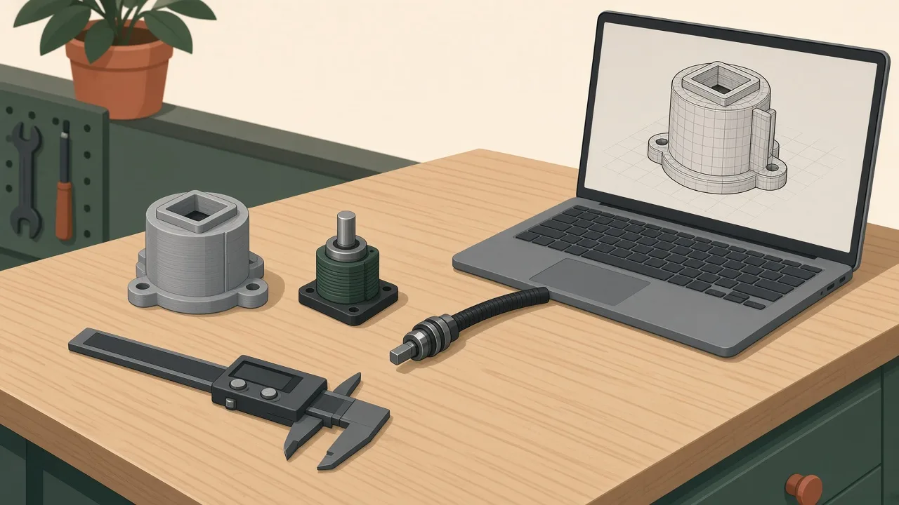
Source: Matt Green (@16vmini) on X, November 4, 2026, and his video Vibe Modeling a Real Car Part, No CAD. This is an independent summary; the builder and the tool makers have not reviewed or endorsed it.
Matt Green is building an electronic dash for a classic Mini. The car’s speed comes from a mechanical speedometer cable, so the new dash needed a way to turn that spinning cable into pulses. His answer was a small printed adapter, designed by talking to an AI instead of drawing it in CAD. It is a neat example of vibe manufacturing: real measurements in, a printed part out.
The problem
A classic Mini’s speedo cable ends in a square drive that turns the needle in the original gauge. A digital dash can’t read a spinning cable. It needs an electrical signal. The fix is to make the cable spin a rotary encoder, which outputs pulses as it turns. That needs a part that grips the square drive, couples it to the encoder shaft, and holds the cable end in place.
How it was made
From the post and video description:
- Photos. He took three reference photos: the face of the encoder, the back of the original speedo, and the cable end.
- Measurements. He measured the encoder and the square drive with calipers.
- Prompt by voice. He talked the description into Claude Code (he names Opus 5.5) rather than typing it.
- Model in code with a preview. Claude built the model in code and opened a 3D preview in the browser, with rotate, cutaway and exploded views and an STL download.
- Tweak and print. He adjusted the flat on the shaft, thinned the flange to 4 mm because his M3 screws are only 6 mm long, and added countersunk holes. The STL went straight into Bambu Studio for a PLA test print.
He says he designed it the day before, printed it, and it fitted. The video recreates the process live. His own summary of the limits is worth repeating: “You still have to measure, and you still have to understand what you’re making.”
The encoder he used is a 600 PPR (pulses per revolution) rotary encoder, which he says cost £16 on Amazon. We are not linking a specific listing.
Workflow you can copy
The same steps work for other mechanical-to-digital adapters, such as a tachometer drive or a cable-driven gauge.
1. Photograph the mating parts
Take clear photos of every face the adapter touches. Photos tell the AI the shape. They don’t give scale.
2. Measure what has to fit
Measure the square drive across the flats, the encoder shaft diameter and any flat on it, the mounting hole spacing, and the length of the screws you actually own.
3. Prompt for a CAD model
Design a 3D-printable adapter that couples a square cable drive
(X mm across flats, Y mm long) to a rotary encoder shaft
(Z mm diameter with a D-flat). Add a housing the cable end clips into,
a 4 mm mounting flange with countersunk holes for M3 x 6 mm screws,
and 0.2 mm clearance on sliding fits. Show a cutaway preview and export STL.
Replace X, Y and Z with your own measurements.
4. Review the preview
Use a cutaway or section view to check the socket depth and wall thickness. Check that the screws reach far enough into the material without poking through.
5. Print a test piece and fit it
Print in PLA first to check fit. If the part will sit near engine heat, a test in PETG or ASA may be wiser, but check the temperatures yourself.
Cost and time
Estimate, not a quote. The builder mentions a £16 encoder. A small adapter like this uses little filament. Your AI tool’s cost depends on your plan. Expect an evening for the first version if you already have a printer, plus extra rounds if the fit is off.
Pitfalls
- Legality and accuracy. Many places require a working speedometer. Calibrate the digital reading against GPS before you rely on it.
- Heat and vibration. Behind a dash is warmer and shakier than a desk. Check that the part and screws stay tight after a few drives.
- Thin flats. A D-flat that is too shallow in the print will slip. Measure the printed bore, not just the model.
- Wiring. The encoder and dash are low-voltage electronics. Fuse the supply and keep wires away from moving parts.
Other light-duty vehicle parts follow the same rules, such as a van accessory mounting bracket. If you want a gentler first project with a shaft fit, try a replacement vintage receiver knob, or start with our guide on how to make a 3D-printable part with AI.
Tools and services
- Claude Code, which the builder used for the model and the 3D preview.
- Calipers.
- A 600 PPR rotary encoder.
- Bambu Studio and a Bambu Lab printer, per the video description; any slicer and FDM printer will work.
Related use cases
FAQ
What does this adapter actually do?
It takes the square drive on the end of a classic Mini's mechanical speedometer cable and uses it to spin a rotary encoder, so an electronic dash can read speed. A housing lets the cable clip on like it would on the original speedo.
Did the builder use any CAD software?
According to his video description, no traditional CAD. He described the part to Claude Code by voice, gave it photos and caliper measurements, and Claude built the model in code with a browser 3D preview and an STL download.
What changes did he make after the first model?
Per the video description, he adjusted the flat on the shaft, made the flange thinner at 4 mm because his M3 screws are only 6 mm long, and added countersunk mounting holes.
Is a 3D-printed speedometer adapter road legal?
That depends on where you live. Many countries require a working, reasonably accurate speedometer. Check your local rules and compare the digital reading against a GPS before relying on it.
Is this article endorsed by the builder or by Anthropic?
No. This is an independent write-up based on the builder's public post and video description. Neither he nor any tool maker has reviewed or endorsed it.