Workshop
8 AI CAD prompts for 3D-printable parts
Copy-and-adapt prompts for ChatGPT, Claude or Gemini that produce printable OpenSCAD parts: brackets, clips, knobs, enclosures, plus prompts for fixing a bad fit.
Sources: this site’s existing how to make a 3D-printable part with AI guide, which already includes a shorter version of these templates, plus the clearance estimates used in first-print fit tips. This page is the standalone prompt pack. Nobody named here has reviewed or endorsed it.
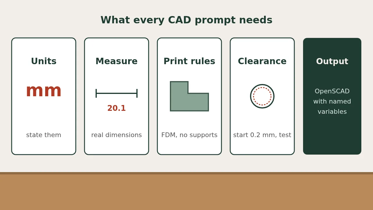
A good CAD prompt states the units, every dimension you measured, how the part will be printed, and the output you want. Leave one out and the model guesses, and it guesses wrong in ways you only find after printing.
The templates below work in any general chatbot that can write OpenSCAD. Replace the text in [brackets] with your own numbers.
The five things every prompt needs
| Element | Why | Example |
|---|---|---|
| Units | Models mix millimeters and inches if you let them | “All dimensions in millimeters.” |
| Measured dimensions | The model cannot see your part | “The rail is 20.1 mm wide, measured with calipers.” |
| Print constraints | Stops unprintable shapes | “FDM, 0.4 mm nozzle, no supports, flat face on the bed.” |
| Clearance | Printed holes come out tight | “Add 0.2 mm clearance on mating faces.” (a starting estimate; test it) |
| Output format | Makes the result editable | “OpenSCAD, every dimension as a named variable at the top.” |
The clearance and wall numbers in the prompts are common starting points for home FDM printers. Your printer and filament will differ, so print a test piece first.
1. The base template
Use this for anything. The other prompts are this one with details filled in.
Write OpenSCAD code for a [part name]. All dimensions in millimeters. Purpose: [what it holds, covers or connects]. Dimensions I measured: [list each one with a name]. It will be FDM printed with a 0.4 mm nozzle, flat on the bed, without supports. Minimum wall thickness 1.2 mm. Add 0.2 mm clearance where it meets another part (a starting estimate). Put every dimension in a named variable at the top with a comment. Set $fn = 64. Before the code, list any assumptions you made.
2. Mounting bracket
Write OpenSCAD code for an L-shaped mounting bracket, in millimeters. Vertical leg: [height] x [width]. Horizontal leg: [depth] x [width]. Thickness: [t]. Two holes in each leg for M[size] screws, clearance diameter [3.4 for M3, 4.5 for M4], centered, [spacing] apart, at least [edge distance] from every edge. Add a 45-degree gusset between the legs so it prints without supports lying on its side. Round the outer corners with a 2 mm radius. All dimensions as variables at the top. This is for a light load only: [describe the load].
3. Snap-on clip for a rod or cable
Write OpenSCAD code for a C-shaped snap clip, in millimeters. It grips a round [rod/cable] of diameter [d], measured with calipers. Inner diameter: d + 0.2. Opening width: 80% of d so it snaps on. Wall thickness [2]. Clip width [10]. Add a flat base [length] x [width] x [3] with one countersunk hole for a [size] screw. Orient it so the C profile lies flat on the bed and the layers run around the clip. Variables at the top, including the opening percentage so I can tune the snap.
4. Replacement knob for a D-shaft
Write OpenSCAD code for a control knob, in millimeters. Shaft: diameter [6.0], with a flat that leaves [4.5] across. Shaft depth: [12]. Make the bore 0.15 larger than the shaft on all faces. Knob outer diameter [30], height [18], with [12] grip flutes around the edge. Add a pointer line 1 mm wide and 0.6 mm deep on the top face, aligned with the flat. Print orientation: top face down, no supports. Variables at the top.
5. Enclosure with a lid
Write OpenSCAD code for a two-part electronics enclosure, in millimeters. It holds a board [length] x [width] x [height including components]. Leave 2 mm of space around the board. Wall thickness 2. Four standoffs under the board’s mounting holes at these positions: [x,y list], height [4], with [2.2] mm pilot holes for M2.5 self-tapping screws. Lid with a 1.5 mm lip that fits inside the box with 0.2 mm clearance per side (a starting estimate). Cutouts: [connector name] on the [side], [w] x [h], centered [z] above the board. Render the box and lid side by side, both flat on the bed. Variables at the top.
6. Start from a photo
Attach a photo of the part lying on grid paper, shot from straight above.
The photo shows a [part] on 5 mm grid paper. Use the grid only to understand the shape. Use these caliper measurements for size, not the photo: [list]. Describe the shape back to me in words and list every dimension you still need. Do not write code yet.
Answer its questions, then send the base template. Making the model ask first catches most wrong guesses.
7. Fix a part that does not fit
I printed the part. Here is what I measured on the print versus the design: [feature]: designed [x], printed [y]. [feature]: designed [x], printed [y]. The [hole/slot/tab] is too [tight/loose] by about [amount]. Change only the variables needed to fix this. Do not restructure the code. Tell me which variables you changed and by how much.
8. Check before printing
Review this OpenSCAD code as if you were about to print it on an FDM printer. List: any wall thinner than 1.2 mm, any overhang steeper than 45 degrees, any hole without clearance, any feature smaller than 0.8 mm, and any dimension that is hard-coded instead of using a variable. Do not rewrite the code. Give me the list only. [paste the code]
Common prompt mistakes
| Mistake | What happens | Fix |
|---|---|---|
| “Make it fit a standard pipe” | The model picks a size | Measure and state the diameter |
| No print orientation | Overhangs and supports everywhere | Name the face that sits on the bed |
| Asking for the STL directly | A broken or imaginary file | Ask for code and render it yourself (see which file to send) |
| Ten changes in one message | New errors appear while old ones are fixed | One change per message |
| Trusting the preview | Wrong scale or a non-solid model | Measure one dimension in the slicer |
What prompts will not fix
No wording makes a chatbot an engineer. Keep these prompts to light-duty parts, and skip anything that carries a person, sits near heat or mains power, or touches food. For the rest of the loop, use the how-to and the first-print fit tips.
FAQ
Which AI is best for these prompts?
Any current general model that writes code can handle them. Dedicated text-to-CAD apps are quicker for simple shapes and usually export STEP. Compare them in our best text-to-CAD tools guide.
Why OpenSCAD and not an STL?
OpenSCAD is text, which chatbots write well. You get dimensions you can change, and you render the STL or 3MF yourself. Asking for an STL directly often produces a broken or imaginary file.
Do I need to install anything?
OpenSCAD, which is free, and your printer's slicer.
The code throws an error. What now?
Paste the exact error message back and ask for a fix to that line only.
Is this page sponsored?
No. Tools are named as examples. None of them reviewed or endorsed it.