Electronics
Five AI-designed PCBs that were built, and what broke
Real boards designed with Claude, Codex and GPT, made at JLCPCB and elsewhere: what was built, and where the designs still failed.
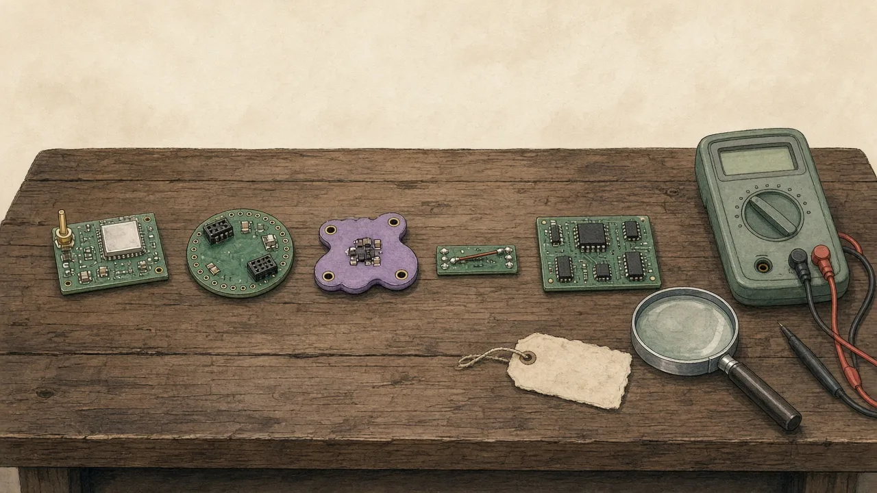
Sources: each build links to its creator’s own write-up, repository or post. All were checked on 9 November 2026. We quote briefly and paraphrase the rest. No photos are reproduced; the illustration is our own. Nobody named here has reviewed or endorsed this article.
Boards “designed by AI” are everywhere in 2026. Most stop at a render. We looked for builders who ordered the boards, powered them up and wrote down what went wrong. Five stood out, and a sixth, the Claude Code lathe controller, gets its own article.
They have one thing in common: all five boards ended up working, and none of them was a single prompt.
At a glance
| Build | AI role | Board | Fab | What went wrong |
|---|---|---|---|---|
| GNSS module | Claude Code + Codex drove KiCad | 4-layer, 25 × 36.5 mm | JLCPCB, with SMT assembly | RF maths and one design rule wrong before ordering; wrong antenna at test |
| VA5 voice-assistant board | Claude Code ran a scripted pipeline | 2-layer, 34 nets | Not stated | Autorouter left a few connections, finished by hand |
| DEF CON badge | GPT for circuit, Claude for firmware; layout by hand | ESP32-S3 badge | JLCPCB, with assembly | A switch shorted the boot pin to ground |
| XIAO battery adapter | Codex edited KiCad files | 2-layer, 22 × 14 mm | JLCPCB, with assembly | Switch contacts mapped wrong; “+” label on the wrong pad |
| VGA logic board | Claude designed circuit and GAL code; routing by hand | 74-series logic | JLCPCB, $6 | One error, fixed with a wire |
1. A 4-layer GNSS module with two agents and one writer
Source: John’s build log on the JLCPCB blog (Traditional Chinese, 3 November 2026) and his MIT-licensed pcb-agent-workflow repository, which includes the ordered KiCad files. JLCPCB supported the manufacturing and assembly, and his post uses partner links. We link to it plainly.
This is the most rigorous write-up we found. The board is a breadboard-friendly breakout for a u-blox MAX-M10S receiver: 25 × 36.5 mm, four layers with two solid ground planes, 3.3 V only, and a passive antenna on a tiny coax connector. Codex did most of the schematic and layout through KiCad’s Python API. Claude Code reviewed it independently and later did the bring-up testing. Every check ran through KiCad 10’s own kicad-cli.
His rules are worth copying. One writer at a time, with a WORKLOG.md handover. Reviewers are read-only. Save a restorable version before every change. Payment, ordering and sign-off stay with the human.
The agents made mistakes, and he documents them:
- Impedance maths. The first 50 Ω calculation used a simplified formula outside its valid range. A cross-check then plugged the wrong constant back in and got 51.12 Ω. He replaced both with a script that implements the full formula.
- A rule that DRC couldn’t catch. A design-rule exception meant to allow a 0.15 mm neck near the antenna also applied to the ground pour. The intended 1 mm clearance shrank to about 0.151 mm, and DRC reported no errors because the rule allowed it. After fixing it, he made a test copy fail on purpose to prove the rule now worked.
- Assembly limits. Two earlier revisions had a supercapacitor backup. JLCPCB’s support told him supercapacitors and battery-type parts weren’t offered for assembly. He removed the backup, which the module’s manual allows.
At first test there were zero satellites. The board was fine: the antenna on his bench was an active one that needs power this board deliberately doesn’t supply. With a passive antenna he got a 3D fix and a steady 1 Hz timing pulse. From first revision to that fix took about five weeks.
2. VA5: the board and the case from one file
Source: Udi Tirosh’s Hackaday.io log, “I let AI design the PCB for my device. I never opened a CAD tool” (19 October 2026).
VA5 is an ESP32-S3 voice assistant for classrooms. A large order meant hand-wiring was no longer practical, so the same jumper wiring had to become a 2-layer board. It has twelve module sockets, a USB-C connector, one button and 34 nets. The hard part was mechanical: the screen, USB port and audio jack had to line up with windows in an existing printed shell.
Claude Code worked inside a repo containing the whole pipeline: build123d for the enclosure and board outline, KiCad 10’s pcbnew API for placement and pours, headless FreeRouting, and kicad-cli for DRC and Gerbers. His six rules:
- One parameter file. The screen’s position is a single number, read by both the case model and the board generator.
- Generate, never hand-edit, so Claude changes the generator, not its output.
- One orchestrator script with named stages. Gerber output is left out of the default “all” run, so you can’t fab a half-routed board by accident.
- Validate the netlist before placing anything, against the real footprints’ pad maps.
- Write down the scar tissue. Each hard-won KiCad and FreeRouting quirk is a comment next to the code, so the agent doesn’t “clean it up” later.
- Keep the human where judgment lives. FreeRouting stops with a few connections unrouted. He finishes those by hand, checks the render and runs DRC himself.
He reports the boards ordered and the case printed, with every window landing on its part. He doesn’t name the fab. His own summary is the best line in this roundup: AI is “extremely good at working inside a codebase with clear rules.”
3. A DEF CON badge, and the switch nobody modeled
Source: Federico Maggi, “I let GPT + Opus build a wearable PCB badge from a paper sketch”, Trustial, 4 August 2026.
Starting from his children’s sketches, Maggi used GPT-5.5, through ChatGPT and then Codex with kicad-cli, to plan the architecture and walk him through the schematic one BOM line at a time. A parts-lookup MCP server filled in LCSC numbers, and easyeda2kicad fetched footprints. He did the layout by hand. Claude Opus wrote the firmware. JLCPCB made and assembled five badges, which he says came to about $66 each including shipping and import tax.
He used adversarial review: a fresh session asked to find faults. It caught real ones, including a regulator feedback pin wired straight to the output instead of to a divider. But the first board would not boot. The ESP32’s boot pin was held low. Neither model, nor he, nor a friend’s half-hour review had spotted the cause: one switch’s internal contacts created a path to ground. The schematic had no model saying which pins were joined inside the switch, so ERC couldn’t see it either. He removed the switch and the badge booted.
His verdict is balanced. The AI was a strong “force-multiplier design consultant” and roughly halved the timeline, he estimates. But it failed at “maintaining an accurate, full end-to-end picture of the whole project”. The badge includes a lithium charger; treat that part as his case study, not a template.
4. A tiny XIAO battery adapter, built twice
Source: Peter (@Peter05704721), “Designing a PCB with Codex and KiCad: From a Real Need to a Tested Board”, an X article, and his follow-up post, both 4 September 2026. He says he is building a commercial AI hardware tool, so he isn’t a neutral party, but his write-up is candid.
The brief was simple: a 22 × 14 mm board between a lithium cell and a Seeed XIAO, with two 1.25 mm connectors, a latching button and a power LED. Codex edited the .kicad_sch and .kicad_pcb files directly and used KiCad for checks and exports. It fixed netlist, part-number and via-size problems until JLCPCB’s import accepted the files. JLCPCB made and assembled it.
ERC and DRC passed. The board didn’t work. The PCB used switch pins 1 and 2, but his meter showed those pins are never connected in either switch position. A bodge wire fixed it. The “+” silkscreen was also on the negative side, which no rule check reads. He did the first power-on with a protected, current-limited bench supply, not the battery.
Later he rebuilt the brief with GPT-6 Astra. It flagged the switch ambiguity before fabrication, but the board grew to 26 × 20 mm and 13 parts. When he posted, the second board hadn’t been built yet.
5. A $6 VGA board from textbook logic
Source: a comment by Hacker News user CyLith in the “Can AI design circuit boards yet?” thread, September 2026. This is the thinnest source here: a first-hand account without photos or files.
Claude Opus 4.8 designed a “fairly textbook” circuit that outputs a monochrome image from an EEPROM over 640 × 480 VGA, using only 74-series logic and GALs, plus the GAL code. He routed the board himself and JLCPCB made it for $6. One error got through, which he fixed with a wire, and “it works just fine otherwise.” It’s a useful counterweight to the bigger projects: a well-documented classic circuit is where an LLM is strongest.
What the five builds teach
1. The physical part is the weak spot. Two of the faults were switches whose internal contacts were assumed rather than measured. The fix is boring: check the datasheet’s internal diagram or measure a sample with a meter, and make sure the symbol shows which pins are joined.
2. Passing ERC/DRC proves the rules, not the board. It didn’t catch a bad rule exception, a missing switch model or a silkscreen on the wrong pad. Test your checks by making them fail, as John did.
3. Write scripts, not reassurances. Netlist validators, impedance scripts, Gerber comparisons and the lathe builder’s clickable trace viewer can be re-run. “I checked it” can’t.
4. Two models are better than one, but not enough. Adversarial and cross-model reviews found real faults in two builds, and missed one in each.
5. Autorouting still plateaus. Where the agent routed, people finished the last few connections, loosened constraints or routed by hand.
6. The human keeps the money and the trade-offs. Ordering, paying, confirming production files and cutting features stayed with the person in every serious build.
A safe way to start
Copy the pattern, not the riskiest circuits. Start with a low-voltage board, such as a carrier for modules you already understand, like the desk mute button. Ask the agent for the KiCad project, a netlist check and a continuity test list. Order a few bare boards first. Power them from a current-limited supply. Lithium charging, mains, motor drives and anything safety-related need qualified review, not a prompt.
Cost and time
Creators’ figures, not quotes. CyLith: $6 for the VGA boards. Maggi: about $66 per assembled badge for five, including shipping and import tax. John’s manufacturing was supported by JLCPCB, so his cost isn’t a guide. The others didn’t publish prices. Time: about five weeks across three revisions for the GNSS module; Maggi estimates the AI roughly halved his schedule. Your quote, shipping and import costs will differ; see ordering from US, European and Chinese services.
Tools that appear in these builds
- Claude Code, Codex, ChatGPT; Claude Opus and GPT model versions as named by each builder.
- KiCad 10, its Python API and
kicad-cli; FreeRouting; build123d;easyeda2kicad. - PCBCraft did not appear in these five builds. For how that open-source editor differs from driving KiCad, see PCBCraft.
- JLCPCB for boards and assembly.
- A multimeter and a current-limited bench supply, used in every build that reports bring-up.
Update, 13 November 2026: Robbi, a desk robot on a Codex-designed board
Source: AceBuilder (@Ace_Builder_), his post of 10 November 2026, the Robbi repository and his build video. Checked on 13 November 2026.
Robbi is a small Raspberry Pi Zero 2 W robot with a screen for a face, a camera, a microphone, a speaker, two encoder motors and a forward distance sensor. For the rebuild, AceBuilder made his “first ever custom PCB, designed (almost entirely) by Codex.” In an earlier post he described a Pi Zero 2 W HAT for the same robot project that GPT-6 Astra had routed through Codex and that he had tested as working.
It’s the most complete open package among these builds. The repository has the Gerbers, the assembly BOM, a pick-and-place file, a schematic PDF and the board settings recovered from the factory’s returned production files: a 75 × 45 mm, four-layer FR-4 board with 59 parts, which includes the power, motor-driver, amplifier and IMU circuits. His parts list points to a JLCPCB quote for fabrication and assembly, and he gives no price.
He’s also open about what isn’t right yet, which is why it belongs here:
- Power. Plugging in a charger can briefly cut the supply and brown out the Pi. He tells builders to shut down and switch off before charging.
- Labels. Several schematic test points keep names from an older design, and one marked as USB detection is actually a motor output. No rule check catches a misleading name, which echoes the wrong “+” label in build 4.
- Mechanics. The latest printed enclosure has only been checked in CAD and the slicer, not printed and assembled. The distance sensor is held with hot glue, and the wiring uses DuPont leads that can work loose.
The license allows personal, non-commercial builds. The board includes battery charging, so the beginner advice above still applies.
A related vendor test. JLCPCB’s blog has a review (first published 14 September, updated 10 November 2026, and promoted on X on 12 November) of GPT-6 Astra designing a two-layer 12 V stereo amplifier in KiCad. KiCad reported zero ERC and DRC violations, but five DRC and four ERC categories were set to be ignored, and JLCPCB says that board has never been fabricated, assembled or measured. It’s a design exercise from a fab, not a build, and it makes lesson 2 above in its own words: a clean DRC is “not manufacturing approval.”
Update: a lab-built comparison
On 9 November 2026, Anthropic and Diode Computers published a demo where Claude Fable 5.2 designed three complete devices: a speakerphone, a voice-assistant hub and a handheld pet. That meant 4-layer boards, enclosures and firmware, and Anthropic says none needed electrical fixes. It’s a vendor demo in a professional fab’s workflow, not an independent build. We cover what it shows and how it compares with the five builds above in Claude designed three working electronic devices.
Related
FAQ
Can AI design a PCB that works?
For simple, low-voltage boards, yes, with a person checking. All five builds here ended up working, but three needed a fix after the boards arrived: two wires added by hand and one switch removed. None was a one-prompt, no-review job.
What goes wrong most often?
In these five builds, the physical part was misunderstood more often than the routing. Two of the faults were switches whose internal contacts the AI, and the person, had wrong. Design-rule checks passed in both cases, because the checker only knows the rules and models it is given.
Which tools did they use?
Claude Code and Codex driving KiCad through its Python interface or by editing project files, kicad-cli for checks and exports, FreeRouting for autorouting, build123d for an enclosure, and parts lookups against LCSC. One builder routed the board by hand and used the AI only for the circuit.
Is a passing DRC enough to order?
No. One builder found a rule exception that silently allowed a 0.15 mm gap where 1 mm was intended, and DRC still reported zero errors. He then proved his rules worked by making a test copy fail on purpose.
Should a beginner copy the battery or charger circuits?
No. Two builds involve lithium cells or charging. Their write-ups are useful as case studies, not as how-tos. A first board should be USB-powered or run from a bench supply.
Is there a complete open-source robot with an AI-designed PCB I can study?
Yes. AceBuilder's Robbi desk robot publishes the Gerbers, BOM, placement file and schematic of its four-layer board, which he says Codex designed almost entirely. His README lists open issues, such as a brownout when a charger is plugged in, and warns that the latest enclosure revision hasn't been physically tested. Treat it as a case study for experienced makers.
Is this article sponsored?
No. Nobody paid for it and the links are plain. Note that JLCPCB supported the GNSS builder's manufacturing, and the XIAO-adapter builder is developing a commercial AI hardware tool. None of the creators or companies reviewed or endorsed this article.