Electronics
Claude Code designed a working PCB for a lathe controller
James Dean Garage had Claude Code design a Pico 2 W board for a lathe controller, then had it made at JLCPCB. What worked, and what to check.
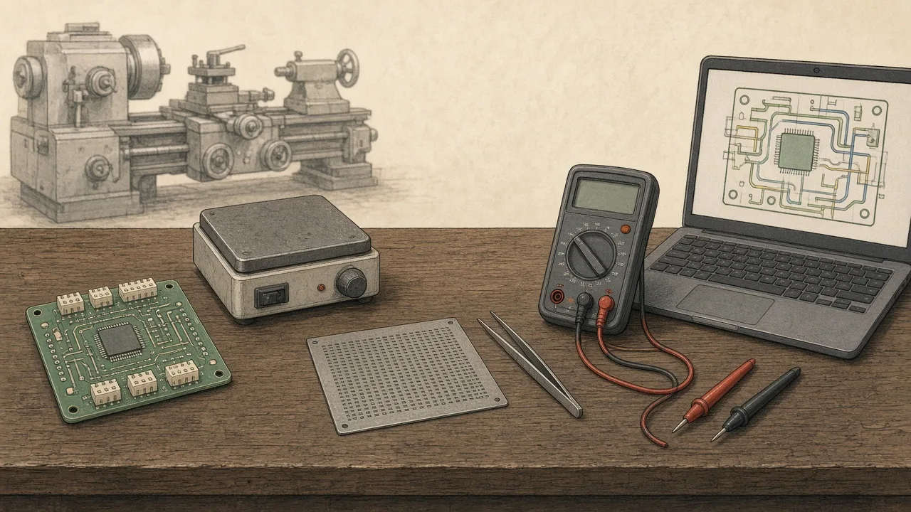
Source: “Claude AI Designed a PCB for My Lathe and I Had It Made. Does It Work?” by James Dean Garage on YouTube, published 11 October 2026. This is an independent summary with short quotes. James Dean Garage, Anthropic and JLCPCB have not reviewed or endorsed it. We are not reproducing frames from the video; the illustration is our own.
Most “AI designed my PCB” posts stop when the parcel arrives. This one goes further. In about 40 minutes of video, a self-described non-electronics engineer shows the files Claude made, the boards from JLCPCB, his first attempt with solder paste and a hot plate, and the board running his lathe. He’s honest about his own mistakes along the way.
Creator video: “Claude AI Designed a PCB for My Lathe and I Had It Made. Does It Work?” by James Dean Garage. The chapters cover the interactive wiring diagram (0:22), the PCB viewer (2:32), his Claude Code setup (5:24), soldering (19:54) and power-up (33:28).
What the board does
The channel has been converting a Clausing 5914 lathe to an AC servo. A Raspberry Pi app he calls Servo Commander runs it. The “tap box” is the small enclosure on the lathe that links everything together. Until now it was hand-wired: a Pico 2 W, a MAX485 RS485 module and a little power distribution block, with a lot of loose wire.
The new board replaces that bundle. According to the video description, it carries:
- a Raspberry Pi Pico 2 W on headers;
- an on-board MAX485 for RS485 to the servo drive;
- DB9 jacks for the X and Z scales, with jumper headers to choose between Sino and TouchDRO pinouts;
- the forward/reverse control jack and an AUX header.
There are two versions. The mill board adds Y and W (quill) scale inputs and moves the AUX header. The jumpers are a nice detail: he only needs Sino pinouts on his lathe, but the board can be reused with the other common scale wiring.
How he worked with Claude
Three habits stand out, and all of them carry over to other projects.
1. Make the wiring checkable before the PCB exists
He first had Claude build an interactive HTML wiring diagram of the hand-wired box. Click a component and it isolates that component’s wires, with a pin table beneath. He used it to wire the first box, and later gave the same file to Claude as the brief for the PCB.
2. Have the agent drive KiCad, then build yourself a viewer
He used a Claude Code project rather than the chat window, because the code session can install tools and run scripts. Claude used KiCad’s Python interface to create the board. In his words: “It gave me the output files and I was off to the races.”
The clever part is how he checked it. He asked for a second HTML file: an interactive 2D/3D board viewer. Clicking a trace shows where it goes, including through vias, and parts can be hidden layer by layer. “I needed a way to validate the traces on the board,” he explains, so that a single wrong trace would not cost him a batch of boards.
He also turns on Claude Code’s bypass-permissions mode so it doesn’t stop for approval at every step. That is his choice. If you copy it, keep the session in a dedicated project folder with version control.
3. Iterate when routing fails
The first prompt wasn’t the last. At one point routing stalled. He puts that down to his own constraints, not the AI: the layout he had asked for was too cramped. The fix was a bigger board and a different assignment of Pico pins, spreading the connections so traces could reach them. Claude then updated the wiring document to match the routed board.
From parcel to working lathe
The boards. He ordered five lathe boards and five mill boards from JLCPCB, plus a stencil. He paid about $7.50 a board and roughly $75 in total, with faster shipping, and the boards took about a week. He paid for them himself.
Assembly. Instead of buying new SMD parts, he desoldered the components from his old MAX485 module and moved them to the new board. He applied paste through the stencil, using a 3D-printed holder, then reflowed on a hot plate he says cost about $27. One protection part was left off because he couldn’t get it easily; the board has room to add it later. After reflow he found he had placed two parts the wrong way round, and fixed them off camera.
Testing. Before applying power he went through a continuity checklist Claude had written (“from this contact to this contact, and what result I should be getting”), then used a bench supply. Claude also updated the firmware for the new pin assignments. At power-up the drive came online, both scales read and the servo jogged. “I think that answers the question,” he says, adding: “this isn’t super complicated, but I don’t care.”
The case. The board didn’t fit the old box. He printed a new one that reuses the original bracket, with clear-filament light pipes for the two status LEDs and a hole for the reset button.
What to take from it
- Start from wiring that already works. The PCB copied a hand-wired box that already ran the lathe. That makes it a carrier board, not new circuit design, and it is the safest kind of first AI-designed board.
- Ask for a viewer as well as Gerbers. A clickable trace map is quick for an agent to make and easy for a beginner to check. It doesn’t replace the fab’s own viewer or a design-rule check, but it catches the “that pin goes where?” class of mistakes.
- Get a test plan with the board. A continuity checklist written alongside the design means you know what the right answer is before you pick up the meter.
- Keep the power side separate. The board only handles low-voltage logic and signals. The servo drive, its supply and the machine’s emergency stop and guarding belong to the drive maker’s manual and a competent person, not to an AI layout.
Pitfalls he hit, or nearly did
- Over-tight constraints. An unroutable layout looks like an AI failure but may be your brief.
- SMD orientation. Diodes and LEDs placed the wrong way round on a hot plate are easy to miss. Check polarity marks before you reflow.
- Paste coverage. He wasn’t sure how much paste was enough and added more on a second pass. Tiny parts need a magnifier; he used magnifying glasses.
- Stencils match one board. His stencil fitted the mill board, so paste for one area of the lathe board went on by syringe.
Cost and time
Creator’s figures, not quotes. About $7.50 per board for ten boards, about $75 in total with faster shipping, delivered in about a week. He estimated JLCPCB assembly at around $5 extra per board. He bought a hot plate for about $27 and solder paste for about $15–16. The paste has a shelf life, so he advises against buying much. Board prices, shipping and import charges change, so read the quote. For EU and US import costs, see ordering parts from US, European and Chinese services.
Tools and services
- Claude Code, KiCad and its Python interface. For an open-source editor that documents the same MCP-style agent control, rather than driving KiCad, see PCBCraft.
- JLCPCB for boards and a stencil.
- Raspberry Pi Pico 2 W, MAX485 transceiver parts, DB9 connectors.
- Hot plate, solder paste, tweezers, magnifier, multimeter, bench power supply.
- A 3D printer for the enclosure and stencil holder.
Related
FAQ
Which AI tool designed the board?
Claude Code, in a code session rather than the chat window. In the video, James explains that it used KiCad's Python interface to place parts and route the board, working from an interactive wiring diagram it had made earlier.
Did the board work first time?
The layout did. The drive came online, both scales read and the servo jogged. He did have to rework two SMD parts he had placed the wrong way round during his first hot-plate reflow; that was an assembly error, not a design error.
Is the board connected to mains power?
No. It carries a Raspberry Pi Pico 2 W, an RS485 transceiver, scale connectors and control jacks on a 5 V supply. The servo drive and lathe wiring are separate. This article is not a guide to wiring servo drives or machine power.
Why not let JLCPCB assemble it?
He wanted to learn hot-plate soldering. He estimated factory assembly at about $5 extra per board, and says the hot plate and paste probably cost him more than assembly would have, but he can reuse them.
Is this endorsed by James Dean Garage, Anthropic or JLCPCB?
No. This is an independent summary of a public video. None of them has reviewed, paid for or endorsed it, and the links are plain links.