Repair
Replacing a broken cargo-net clip from photos, with no CAD
Mechanical engineer Michael Lydick asked ChatGPT to rebuild a glued cargo-net clip from photos and grid paper, then resin-printed a near-match.
Source: Michael Lydick, I’m an Engineer. This ChatGPT Test Scared Me., on Hey it’s me, Michael, published 1 November 2026, about 12 minutes 18 seconds. This is an independent summary. Michael Lydick, the channel, OpenAI, Autodesk, Creality and Olight have not reviewed or endorsed it. Nothing in the video indicates a sponsor.
Michael Lydick, a mechanical engineer and maker, tries to get a replacement part out of ChatGPT without opening CAD. The useful half of the video is a light repair: a broken cargo-net clip, photos on grid paper, and a resin print he stacks on the original. It is a small example of vibe manufacturing aimed at replacement parts, not at safety hardware.
He frames the video, seriously and not as a throwaway line, as a note to engineers, draftsmen, and CAD people. On screen: “0-CAD FIELD REPORT OCT-2026” and “Engineers. Draftsmen. CAD people. THIS ONE’S FOR YOU.” He says CAD professionals are where software programmers were two years ago, and that AI is coming for their jobs next. Names for Claude, Gemini, and OpenAI appear. That is his framing. This article does not take a side on it.
A flashlight scan, then a real STEP
Before the clip, he scans a small rectangular orange-and-black Olight flashlight with a Creality scanner. The laptop shows Creality Scan v4.3.1. The mesh is messy and blue, with gaps where the scanner could not reach. He calls it about a “quarter million” triangles. The graphic shows 234,000.
He imports that mesh into ChatGPT, in a code-interpreter, data-analysis style view. He never names a model version. The AI first heals the mesh so it is watertight, then he asks for a clean version. ChatGPT returns an editable STEP. A graphic says 234,000 triangles reduced to 119 CAD faces.
He opens that STEP in Fusion 360 and shows flat planes, fillets, and a recessed bezel. Set next to a simple toy-rocket AI demo, he says it “blew my freaky-freak mind.” Fusion is for this flashlight solid only. He does not use it to design the clip.
Photos of a glued clip
The second test is a broken black plastic cargo-net clip, glued back together, with the crack still visible. It is the piece that extends a cargo net out to hooks on the wall. He sets it on 2 mm grid paper.
He measures it with a tool he calls a “micrometer”. The tool on screen is a digital caliper. Readings visible on that caliper are 8.59 mm, 16.57 mm, and 8.85 mm. Those are numbers shown in the video, not sizes we measured on a part.
He uploads a batch of nine photos: some of the clip on the grid, some of the caliper on the clip. In short, he asks ChatGPT for an STL that mimics the photos closely, notes that the piece is broken and glued, says he has dimensioned a few places for scale, and asks for a file he can print on a resin printer. An on-screen graphic reads “MEMORY ON”. He credits ChatGPT’s Memory feature, which he says remembers past projects and is getting smarter quickly. That is his comment.
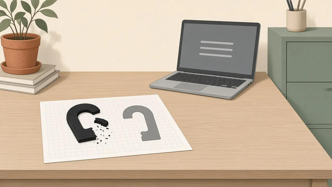
The first result shows a run of 5 minutes 44 seconds. File names on screen include Cargo_Net_Extender.stl and Cargo_Net_Extender_CAD_Package.zip. He prints that first version in black resin. The model was so literal that it copied the irregular crack and glue line into the solid. That failure is the useful one: a close match to a photo will copy the damage in the photo.
A marked-up photo, then a taper he had forgotten
He uploads an annotated photo, with a yellow dashed line and a yellow circle, and tells it to clean the irregular edge where he glued the piece. Short quotes from that note: “That’s supposed to be a radius, and those lines are supposed to be flat faces.” The next black resin print smooths the broken joint into a clean curve.
Around this stage a tracker, while a V3 is on screen, reads “≈ 20 MIN IN - CAD USED - 0”. Another graphic reads “2 MM GRID - READ BY THE MODEL.” He says ChatGPT read the 2 mm grid from the photos to scale the part. The chat states the original piece as 60.60 mm tall by 51.00 mm wide. At that checkpoint the AI’s design was roughly 3 percent larger. That 3 percent is what was said and shown then. We did not measure the prints, and the final print is not assumed here to have stayed 3 percent large.
He then notices a mistake of his own. He had not told it that the original part tapers at the lower hook. A graphic contrasts a white rectangle, “LOWER HOOK WALL PROFILE - CURRENT = NO TAPER”, with an orange trapezoid, “ORIGINAL = TAPERED.” He prompts the taper in. The miss was his, not only the model’s.
The final STL is printed in gray resin. The printer brand and model are not named, and they are not clearly shown: generic wash and cure gear, and boxes labeled resin and SLA. He places the gray print beside the black original, then directly on top of it. He calls the gray print “nearly indiscernible”. A graphic labels it a “Near-identical copy.” That is his wording, plus the stacked comparison he shows. It is not a measurement we took.
Timing graphics read “~30 MINUTES” and, later, “BROKEN HOOK -> FINISHED MODEL 30-40 MIN”. He says he went from a broken part to a finished printed model in about 30 to 40 minutes without opening Fusion 360. He also says he did not use CAD, and speaks of “no engineering skills” for this clip. That is his claim about not opening CAD. He still measured, marked up photos, caught the missing taper, and printed several versions. Judgment did not leave the job.
Resin supports leave small divots, rough bumps along the side face of the gray print. He says they can be sanded away.
He teases a later video about connecting ChatGPT to Fusion for multipart constrained models. He does not demonstrate that here. A different public demo, Claude driving Fusion, is John Saunders’s STL rebuild.
He closes with a warning that people who do not adapt are “kind of that green mile, dead man walking.” One line is enough. This page is about the clip.
David of Making for Motorsport later pointed at this video, which he called “Hey, It’s Me, Michael’s video”, and tried a harder test. He did not say Michael’s surname. That follow-on is vibe-modeling an inlet manifold from scans. Michael does not mention David here.
What this shows, and what it does not
| What the video shows | What it does not show |
|---|---|
| A messy flashlight scan became a STEP he opened in Fusion | A named ChatGPT model, plan, or price |
| Nine photos on 2 mm grid paper, plus caliper shots, produced an STL | That we measured the clip or the prints |
| The first resin print copied the glue crack | A perfect first file |
| A marked-up photo asked for a radius and flat faces | That the model knew which edges were damage |
| At about 20 minutes, CAD used was zero, and the design was about 3 percent large | That the finished gray print was still 3 percent large |
| He had to ask for a taper he had forgotten | That the model invents missing shape on its own |
| A gray print stacked on the original, which he calls nearly indiscernible | A dimensional inspection, or a named resin printer |
| Support divots he says can be sanded | A how-to for copying a patented part, or for replacing safety hardware |
This is a light cargo-net clip. It is not a child seat, a helmet, or a load-bearing hook beyond the clip he showed. Do not treat the method as a way to copy a commercial part you do not have the right to reproduce.
A loop for another light replacement
The same shape of work can apply to a knob, a cover, or a small hook you are allowed to replace. It stops at anything that holds a person or a rated load.
- Photograph the broken part on a scale. Grid paper, a ruler, or a coin in the same shot. Take more than one angle. Include the damage, then be ready to tell the model which edges are damage.
- Measure a few sizes. A digital caliper is what was on screen here, even though he called it a micrometer. Write the numbers down. Photos do not set the scale by themselves.
- Generate a first STL and print it. Expect the first file to copy dirt, cracks, and glue. That is a reason to print a small test, not a reason to trust the preview.
- Mark up the actual defect. A dashed line on a photo, plus a sentence about which edges should be flat or radiused, is more useful than “make it better”. If you forgot a taper, a draft angle, or a hole, say so. That miss is yours.
- Print again and compare. Stack the print on the original, or hold them together. Sand support marks before you judge a flat face. “Nearly the same” is a visual claim until you measure both.
Pitfalls
- Literal damage. A prompt that says “match the photos” will rebuild the crack. Say which edges are broken.
- Forgotten shape. The lower hook was tapered, and he had not said so. Walk the real part and name every change in section.
- A checkpoint is not the final part. About 3 percent large was the figure at the 20-minute mark. Do not carry that number onto a later print you have not measured.
- Support marks. Resin divots sit on faces you may care about. Plan to sand them, or move the supports.
- Identical is his word. The stacked gray print looked near-identical to him. We did not put calipers on either part.
- The wrong job. A cargo-net clip is not a pattern for a seat fitting, a helmet part, or a hook that carries people.
Tools he used
- ChatGPT, in a data-analysis style view, with Memory shown as on. He does not name a model version.
- Creality Scan v4.3.1, for the flashlight mesh only.
- Autodesk Fusion 360, for opening the flashlight STEP only. Not for the clip.
- A resin printer he does not name, with black prints of the early versions and a gray print of the final STL.
- 2 mm grid paper and a digital caliper. He calls the caliper a micrometer.
Related
The harder follow-on, scans rather than photos, and not a part to run, is vibe-modeling an inlet manifold from 3D scans. Measuring a scan in a local tool, with an optional agent, is ScanRuler. Rebuilding an STL as parametric Fusion CAD is John Saunders’s Claude demo. The usual loop is how to make a 3D-printable part with AI. When the first file copies a defect, see why AI-generated 3D prints fail and the first-print fit checklist. A light shaft fit with photos and calipers is the classic Mini speedo adapter.
FAQ
Did he use CAD to design the clip?
Not for the clip. An on-screen graphic reads that CAD used was zero. He opened Fusion 360 only for an earlier flashlight STEP. The clip came from photos, grid paper, and prompts, then several resin prints.
Why did the first print copy the crack?
The first STL copied the glued break. He had asked for a close match to the photos, and the crack was in those photos. He then marked the irregular edge and asked for a smooth radius and flat faces.
How did ChatGPT get the scale?
He put the clip on 2 mm grid paper and uploaded nine photos, some with a digital caliper in frame. An on-screen note says the model read that grid. The chat stated the original as 60.60 mm by 51.00 mm. We did not measure it.
How close was the final print?
He stacked a gray resin print on the black original and called it nearly indiscernible. A graphic labels it a near-identical copy. That is his comparison, not a measurement we took. At an earlier checkpoint the design was about 3 percent large.
Is this article endorsed by Michael or the companies named?
No. It is an independent summary of a public video. Michael Lydick, the channel, OpenAI, Autodesk, Creality and Olight have not reviewed or endorsed it.