Vehicles
Vibe-modeling an inlet manifold from 3D scans, with no CAD
David at Making for Motorsport asked ChatGPT to design an inlet manifold between two incomplete 3D scans without opening CAD, then printed one PLA half.
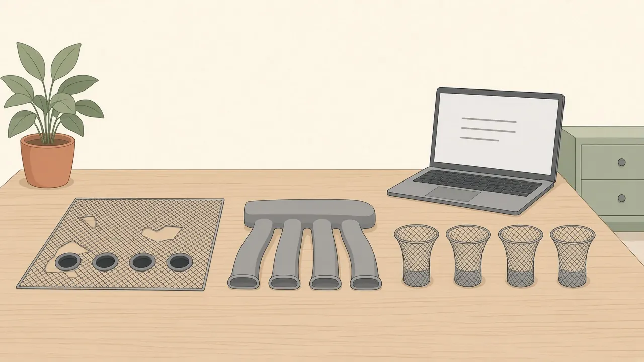
Source: David Fox of Making for Motorsport, in the video Vibe-Modeling is here…. No CAD skills needed - Complex part creation from scans in AI! on the channel Making for Motorsport, published 3 November 2026, 13 minutes 20 seconds. This is an independent summary. David, Making for Motorsport, OpenAI, Autodesk, Bambu Lab and Creality have not reviewed or endorsed it.
David scans and prints parts for the channel. In this video he asks ChatGPT to design an inlet manifold that sits between two incomplete 3D scans, without opening a CAD package to create it. It is a public demonstration of vibe manufacturing: scans and prompts in, a file out. It is not a how-to for a running intake manifold.
He printed one half, in PLA, and held it up at his desk. He did not fit it to the engine, and he did not run the car with it. A 3D-printed PLA manifold is not a safe, heat-appropriate, or road-ready engine part. Do not print an intake, a fuel part, a brake part, or any other safety-critical part from an AI file and bolt it on.
Vehicle projects on this site are accessory brackets and similar light parts. An inlet manifold is an engine air-path part: heat, vibration, vacuum and pressure, and reliability. Read the video as a look at what the model returned on a desk, not as a pattern to copy onto an engine.
What he set out to test
The video opens on a 3D model of an engine and a manifold. He says it has “nailed it”, and that the stud positions are right. The channel sting reads “MAKING FOR MOTORSPORT / Maximum Speed Minimum Money”. He introduces himself as David, and the channel as Making for Motorsport, “where we use digital tools like 3D scanning and 3D printing to make more, go faster, and spend less.”
AI is the new tool in the bag. He had already tried ChatGPT on this kind of job. He then watched a video he calls “Hey, It’s Me, Michael’s video”, and the thumbnail on screen reads “NO 3D SCANS. NO CAD. IT’S OVER”. The public video that matches, from the same week, is Michael Lydick’s I’m an Engineer. This ChatGPT Test Scared Me., published 1 November 2026 on Hey it’s me, Michael. He wanted a harder test, because he is an engineer and wants to know “how far away” extinction-via-AI might be. This article does not recap Michael’s video.
An on-screen flashback reads “PREVIOUSLY: MY PIKA MANIFOLD PROJECT”. In a recent Creality Pika review he had already created an inlet manifold between two 3D scans. CrealityScan 4.3.2 is visible in that footage. This time he wants to know if ChatGPT can do the job with no CAD at all. The video also shows a dirty engine bay with four carburettors, on what the footage presents as a Dutton kit car.
He later names the engine file as Dutton Engine.stl. A cleaned result is shown as dutton_eng_clean_decimate_v1.stl. Other names on screen include Carbs.stl, Carbs Repaired.stl, and Word documents titled Hyper Carbs Scan and Hyper Engine Scan. This write-up does not say what those documents contain.
His YouTube description, as copied on third-party pages, offers scan data and chat transcripts in a Google Drive folder. We have not opened that folder, and we are not listing what is in it. On camera he also says he will put the original, unaltered 3D scans on Patreon, where he mentions bi-weekly updates.
Cleaning and lining up the scans
The carburetor scan is a messy capture of four carbs, with a lot of missing data. He says it is over a million triangles and has over 200 open boundary areas. Cleaning it is not essential, he says. He wants to see what the AI does with it.
ChatGPT made a repaired file next to the old one. He says it did a reasonable job and kept the key information, about what any 3D scanner software might do. On-screen text reads “Processing time was 31mins”.
The engine scan is incomplete and, as he puts it, “not ideal”. It includes the bulkhead and extra geometry, and it sits out of line with the global coordinate system. He mentions the printer bed while describing that odd position. He asks ChatGPT to change the orientation of Dutton Engine.stl.
After about 11 minutes the result is a cleaned, centered engine. The extra bulkhead material is gone, and he says it is “absolutely on the middle.” He looks impressed. The processing ran in the cloud, not on his computer. He had the machine in quiet mode, so the fan stayed quiet. His point: you do not need a very powerful computer if this work happens in the cloud.
He then asks for a new STL that combines the repaired carbs and the aligned engine, with the carbs placed where ChatGPT thinks best. He says not to create the inlet manifold yet.
After about 16 minutes the carbs sit roughly in front of the engine, the wrong way around. The fresh-air inlet trumpets point at the engine. He jokes that it had a 50/50 chance. He prompts a flip. The carbs then face the right way, but they sit too far from the engine in space.
Off camera, he asks ChatGPT to move them about 50 millimeters closer (“50 mil”) and to angle them so the inlet is up and the overall inlet tract goes downhill most of the time. After about another 10 minutes he says the placement is “pretty much exactly where I wanted them.”
The manifold, and a note he did not ask for
He dictates a detailed prompt. In short, he asks for a continuous flange on the engine side so it can bolt up to the studs visible on the head; a runner from each port on the head to each carburetor body; runners as smooth as possible, at least 5 mm thick in the wall; and ribs tying the outer carbs back to the main mounting flange. He also asks for STL and STEP, in the same global coordinate system as the original scans, so an overlay should line up.
ChatGPT asks to use Fusion. His on-screen reply is “I don’t want you to use Fusion please”. Refusing Fusion is the point of the test. ChatGPT then asks how the manifold should meet the carburetor outlets. He chooses option 1, “Flexible sleeves (Recommended)”.
The chat’s own notes mention fastener access. Some areas cannot take a straight socket, so you would need an open-ended spanner. Logs on screen mention a 2.5 mm clearance and a 5.47 mm minimum runner wall. Those two numbers are what ChatGPT reported in the chat. We have not measured them. He is impressed by the fastener note. He says he has often forgotten tool access in his own designs and needed a second prototype, and he did not ask for that point explicitly.
The file finishes after about 1 hour 3 minutes. The ChatGPT view in the video is a code-interpreter, data-analysis style screen running Python. He never names a model version. This article does not guess one.
He looks at the gray manifold in mesh software. The sidebar matches Autodesk Meshmixer, with tools such as Sculpt, Stamp, Edit and Analysis. He does not name that program. Laid over the engine and carburetor scans, he says it lined up, and that the stud positions are right. He notes that in one place the scan does not even show a full stud, but the model inferred a stud and a circle and allowed for the whole circle. The ribs run back to the flange, as he asked, and the runners line up with the carbs. “That does exactly what I asked for.”
His earlier Fusion design, and a STEP he can still edit
He puts the AI manifold next to the one he designed himself in Fusion from the same scan data. His design is shown in green, with a blockier flange and blockier runner bases. The AI version looks smoother and more organic, with a thinner continuous flange. He is impressed by that. This is the visual comparison he shows, and his reaction to it. The two designs are not claimed here to be the same size, and neither is claimed to flow better or to be stronger. We did not measure them.
He opens the STEP in Autodesk Fusion 360. He says it is what he asked for, and that it appears prismatic. He sketches on a flat face and extrudes, then fillets and adds material on semicircle features he does not like. The demonstration is that he did not need CAD to create the part, and that he can still change the STEP in CAD afterwards.
One white PLA half, not fitted
He imports the STL into Bambu Studio. The printer profile on screen is a Bambu Lab X1 Carbon with a 0.4 mm nozzle. The part is too big for the build plate, even after he rotates it.
He asks ChatGPT to split it. After about 20 minutes he has two STLs with an overlapping interlocking section. He says that is not the split he prefers. He would rather go back and ask for clear faces. He prints anyway.
The filament dropdown changes from “Bambu PETG-CF” to “Bambu PLA Basic”, in white. He says it sliced perfectly well. He prints only one half, because he is on a time frame. He does not state a filament cost or a print duration. A timelapse shows an enclosed printer with a Bambu Lab logo. At his desk he holds up a white printed half, with two runners. He does not offer it to the engine, and he does not claim a fit-check on the car.
He calls it “A custom-made 3D printed inlet manifold made to my specific requirements”, and says he has not touched a CAD package to create it: prompts, the scans, and, he adds, possibly a significant amount of the earth’s resources. He thinks the part itself is pretty good. The runners look smooth, and it did what he asked. He also says the scans were incomplete and “not fantastic”, and that the models could infer information you would have thought takes a human to see.
He leaves a question open, and this article does not answer it for him. Is this “the great democratization of design”, with no CAD package, no powerful computer, and no space mouse, just a ChatGPT membership and prompts? Or is it “the ensloppification of all human effort and knowledge”, his word, with years of training “down the toilet”? He asks viewers to comment.
What this shows, and what it does not
| What the video shows | What it does not show |
|---|---|
| ChatGPT repaired a messy carb scan and reoriented a messy engine scan | That every scan will clean up this way |
| The carbs arrived backwards, then too far away, then about 50 mm closer | A measured fit on the real engine |
| STL and STEP came back without him using Fusion to create the part | A named ChatGPT model, plan, or price |
| He judged that an overlay lined up, including a stud the scan did not fully show | That we checked those sizes, or that the AI manifold matches his Fusion design |
| The chat noted fastener access he had not asked for | That the 2.5 mm clearance or the 5.47 mm wall are measurements we verified |
| One white PLA half, printed and held at his desk | A second half, a fit on the engine, a leak test, or the car running |
| He could still edit the STEP in Fusion afterwards | A safe, heat-appropriate, road-ready intake |
A loop for a non-safety part
The same shape of work can apply to a fixture, a mock-up, a fit-check pattern, or a light bracket between two scanned parts. It does not apply to an intake, a fuel part, a brake part, or anything else that is safety-critical. Do not print those from an AI file and bolt them on. A PLA print of an engine air path is a desk object.
- Scan the mating parts. Keep the raw scans. Write down what is missing. A hole in the mesh is not a feature the model may invent without you checking it.
- Clean and align. Ask for a repair and one shared coordinate system before you ask for the new part. In this video the carbs arrived backwards, then too far away. Both mistakes were obvious once he looked.
- Prompt the part between them. State the wall thickness in millimeters, how it mounts, and what it must not do. Ask for STL and, if you will edit it, STEP. For a fixture or a mock-up, say that it is a fit check, not a loaded part.
- Overlay-check, then open the STEP. Put the new mesh on the scans. Look at every face that has to meet a real edge. Open the STEP if a face needs to change. A smooth picture is not a measurement.
- Split only if the plate demands it, and print a test. If the split is an interlock you did not want, ask again for flat faces before you commit plastic. Print one section. Check it against the real parts. Stop if the job has turned into an intake, a fuel part, a brake part, or anything that holds a person.
Design a 3D-printable fit-check mock-up that sits between
two scanned parts. It is a fixture or a pattern, not a
loaded part and not a safety-critical part. Align both
scans to one coordinate system, use the wall thickness
I give in millimeters, add clearance around the holes I
mark, and export STL and STEP. List any gap in the scan
that you filled in, instead of hiding it.
Use your own wall thickness and your own holes. Do not point that prompt at an engine intake.
Pitfalls
- Inferred geometry. He says the model filled in a stud the scan did not fully show. That can look clever, and it can be wrong. Overlay the file on the scan, then measure the real part. A smooth mesh is not evidence.
- Heat and duty. PLA on a desk is not an inlet manifold. Heat, vibration, and vacuum and pressure are outside this demonstration. Buy a part made for the engine, or have someone qualified design one.
- The split. An overlapping interlock was not the joint he wanted. A joint you did not draw can still print, and still fail to assemble the way you expect.
- Cloud time. The waits he states were long, and the work ran in the cloud. A quiet laptop fan does not mean the file is right.
- You still have to understand the part. He could see backwards carbs, a flange that looked thinner than his own design, and a tool-access note he has missed in his own work before. The prompts did not replace that judgment.
Tools he used
- ChatGPT, in a code-interpreter style view running Python. He does not name a model version.
- Autodesk Fusion 360, which he refused as the generator, then used to compare his earlier manifold and to edit the STEP.
- Mesh software whose sidebar matches Meshmixer. He does not name it.
- Bambu Studio, with a Bambu Lab X1 Carbon profile and a 0.4 mm nozzle on screen. The printer in the timelapse shows a Bambu Lab logo. He sliced white Bambu PLA Basic and printed one half.
- Creality Pika, which he names as the scanner from the earlier manifold project, and CrealityScan 4.3.2, visible in that flashback.
Related
A light vehicle part, with measurements and a test fit, is the classic Mini speedo-cable adapter. The usual measure-and-prompt loop is how to make a 3D-printable part with AI. How a chatbot normally writes CAD code, as distinct from this one demo, is AI CAD tools vs ChatGPT. When a file looks right and prints wrong, see why AI-generated 3D prints fail and the first-print fit checklist.
The clip David pointed at is Michael Lydick’s cargo-net replacement from photos. A free local tool for measuring scans, with an optional agent, is ScanRuler. Connecting Claude to Fusion, instead of refusing it, is John Saunders’s STL rebuild.
FAQ
Did he use CAD to create the manifold?
Not to create it. He told ChatGPT not to use Fusion. He later opened the STEP in Fusion 360 to compare it with a manifold he had designed earlier and to edit a few faces. The model itself came from prompts plus the scans.
Did he print the whole manifold?
No. The STL was too big for the printer plate even after rotation. ChatGPT split it into two interlocking halves. He printed one half, in white PLA, because he was short of time.
Did he fit the print to the engine?
No. He held the white half up at his desk. He did not offer it up to the engine, and he did not claim a fit-check on the car.
Is a 3D-printed PLA inlet manifold safe to run?
No. A 3D-printed PLA manifold is not a safe, heat-appropriate, or road-ready engine part. This article is a report of a desk demonstration. Do not print an intake, fuel part, brake part, or other safety-critical part from an AI file and bolt it on.
Is this article endorsed by David or the companies named?
No. It is an independent summary of a public video. David, Making for Motorsport, OpenAI, Autodesk, Bambu Lab and Creality have not reviewed or endorsed it.