Workshop
Advanced guide: 3D printing materials, lasers, CNC and PCBs
An in-depth reference for making parts: printing processes, filament and resin, design rules, laser types and safety, CNC, sheet metal, PCBs and file formats.

Sources: manufacturer knowledge bases and design guides (Bambu Lab, Prusa, Formlabs, xTool, SendCutSend, Protolabs, JLCPCB), standards and regulators (IEC 60825-1 via the UK government’s laser safety advice, OSHA), university safety offices, and UL Research Institutes. Figures are quoted with their source; ranges change between brands, so the product’s own datasheet wins. Nobody named here has reviewed or endorsed this guide.
New to all this? Start with the beginner’s guide. This page is the reference you come back to when you need to choose a process or material, set a tolerance, pick a laser, or tell an AI exactly what to draw.
How to use this guide
Each section is self-contained. A practical order for a new part:
- Process: printed, cut, machined, bent or a board? The chooser covers the big decision; the process table below covers the detail.
- Material: what heat, load, chemicals and sunlight will it see?
- Design rules: walls, holes, overhangs, orientation, clearances.
- Safety: fumes, resin handling, laser class and eyewear.
- File: the format the machine or shop actually wants.
- Prompt: put all of the above into numbers the AI can’t misread.
3D printing processes compared
Protolabs Network publishes general limits for each process in its thin-wall design guide. These are service-bureau guidelines, not guarantees. Your own printer may do better or worse.
| Process | Min wall (supported / free) | Min feature | Layer thickness | Accuracy | Finish | Warping risk |
|---|---|---|---|---|---|---|
| FDM (filament) | 0.8 / 0.8 mm | 2.0 mm | 100–300 µm | ±0.1–0.2 mm | Layer lines visible | High |
| SLA (resin) | 0.5 / 1.0 mm | 0.2 mm | 50–100 µm | May shrink in post-cure | Smooth | Low–moderate |
| SLS (nylon powder) | 0.8 / 1.0 mm | 0.5 mm | 100 µm | ±0.3 mm | Matte, grainy | Low |
| MJF (nylon powder) | 0.7 / 1.0 mm | 0.5 mm | 80 µm | ±0.3 mm | Clean, detailed | Low |
| DMLS (metal) | 0.4–0.8 / 0.8–1.5 mm | n/a | n/a | Geometry-dependent | Rough | High |
Source: Protolabs Network (hubs.com), “DFM tips for 3D printed parts with thin walls”. Values copied as published.
FDM: filament printing
A heated nozzle lays molten thermoplastic down line by line. It’s the cheapest process and the one most people own. Its weakness is between the layers: Protolabs Network’s SLS guide notes that FDM parts are “significantly weaker in the Z-axis”. The FDM overview puts common layer heights at 50–400 microns, with 200 microns as a practical compromise.
Resin: SLA, DLP and MSLA
A light source cures liquid photopolymer resin layer by layer. Formlabs’ printer guide explains the three variants: a scanning laser (SLA), a projector (DLP), or a UV backlight masked by an LCD panel (MSLA, the common low-cost type). Parts are smooth, detailed, watertight and close to isotropic, but need washing and post-curing. Protolabs Network lists desktop SLA accuracy at ±0.5% and industrial at ±0.15% in its SLA overview.
SLS and MJF: powder bed fusion
A laser (SLS) or a fusing agent plus heat (HP’s Multi Jet Fusion) fuses nylon powder. The loose powder supports the part, so overhangs and internal channels need no supports. Protolabs Network describes SLS parts as near-isotropic, with PA 12 (nylon 12) the most common material. You’ll mostly buy these from a service. Formlabs’ comparison puts benchtop SLS printers just under $30,000.
Metal: DMLS and SLM
A laser melts fine metal powder. Protolabs Network’s metal guide gives layer heights of 20–50 microns and dimensional accuracy of about ±0.1 mm, and notes that holes and threads are often machined afterwards to hit tight tolerances. For a small bracket, sheet metal or CNC is usually far cheaper; metal printing earns its cost on shapes that can’t be machined.
FDM filament materials
The table merges Bambu Lab’s filament guide (nozzle and bed temperatures, enclosure, hardened nozzle, drying) with Prusa’s material guide for comparison. Temperatures vary by brand; the number printed on your spool wins.
| Material | Nozzle °C (Bambu) | Nozzle °C (Prusa) | Bed °C (Bambu, glue) | Enclosure | Hardened nozzle | Dry before use (Bambu) |
|---|---|---|---|---|---|---|
| PLA | 190–240 | 185–235 | 35–65 | Not needed | No | Recommended, 55 °C 8 h |
| PETG | 240–270 | 215–270 | 60–80 | Recommended for layer strength | No | Recommended, 70 °C 8 h |
| ABS | 240–280 | 230–255 | 90–100 | Recommended | No | Recommended, 80 °C 8 h |
| ASA | 240–280 | 220–275 | 90–100 | Recommended | No | Recommended, 80 °C 8 h |
| TPU (flexible) | 200–250 | 220–260 (Flex) | 30–45 | Not needed | No | Required, 70 °C 8 h |
| PC | 260–290 | 270–275 | 100–120 | Recommended | No | Required, 80 °C 8 h |
| PA (nylon) | n/a in table | 240–285 | 90–110 | Recommended | No (unfilled) | Required, 80 °C 8–12 h |
| PLA-CF / PETG-CF | 210–240 / 240–270 | n/a | 35–65 / 60–80 | As base material | Yes | Recommended |
| PA-CF/GF | 260–300 | 225–290 (composites) | 90–110 | Recommended | Yes | Required, 80 °C 8–12 h |
| PET-CF/GF | 260–300 | n/a | 80–100 | Recommended | Yes | Required |
| PPS-CF/GF | 310–340 | n/a | 100–120 | Required (Bambu: H2 series and X1E only) | Yes | n/a |
Bambu Lab’s enclosure guidance: ABS, ASA, PC, PA and their fiber-filled versions need higher bed and chamber temperatures “to suppress warping and layer separation”. Bambu drying values are for a blast drying oven.
Bambu’s guide also rates heat deflection, impact resistance and tensile strength on a five-star scale. In short: PLA scores two stars for heat and three for tensile strength. PETG gains heat and impact resistance but loses some tensile strength. PC scores four on all three. Nylon-CF and PET-CF score five for heat and tensile strength but only one to two for impact. TPU scores five for impact and one for strength.
Choosing a filament
- PLA: stiff, easy, low warp. Indoor parts only. Bambu says it is not recommended at about 50 °C or higher, where it “may slowly degrade, soften, and deform”.
- PETG: tougher, more heat-tolerant, good layer adhesion. Prusa’s PETG page describes it as popular for “mechanical parts, holders, clamps, and waterproof parts”.
- ABS and ASA: more heat-tolerant. ASA is the usual pick outdoors. Both need an enclosure and ventilation (see fumes below).
- TPU: flexible: gaskets, bumpers, grips. Feed problems are common in multi-material units; Bambu lists soft TPU as unsuitable for its AMS.
- PC: tough and heat-resistant, but warps. Needs an enclosure and dry filament.
- Nylon (PA): tough and wear-resistant, very moisture-hungry. Dry it before every print.
- Carbon- and glass-fiber blends: stiffer and more dimensionally stable, but more brittle. They need a hardened nozzle.
- PEEK, PEI (Ultem), PPS: engineering polymers for heat and chemicals. Prusa’s PEI 1010 guide calls for a printer that holds 410 °C at the nozzle, 150 °C at the bed and at least 90 °C in the chamber, with filament dried at 150 °C for 6–8 hours. 3DXTech’s ThermaX PEEK page gives a 360–450 °C hot end, 120–160 °C bed and a 70–150 °C actively heated chamber, and warns that “most standard desktop printers can’t reliably maintain these conditions”. For one-off parts, order these from a service.
Drying, nozzles and enclosures
- Moisture. Bambu explains that damp filament boils in the nozzle, causing “stringing, under-extrusion, holes, rough surfaces, and reduced strength”. Dry it per the table and keep it sealed with desiccant. Prusa notes that PEI left out of a dry box absorbs moisture “in dozens of minutes”.
- Hardened nozzles. For CF, GF and particle-filled filaments (including glow and marble PLA), Bambu says not to use brass or stainless nozzles because “they wear out quickly”. It also advises against 0.2 mm nozzles for these materials and recommends 0.6 mm hardened steel first.
- Enclosures. These keep the air warm and stable for warp-prone materials. With PLA and PETG, Bambu suggests opening the door or lid when the bed is hot, so the filament doesn’t soften inside the extruder.
Resin and powder materials
- Resin. Formlabs lists standard, engineering (ABS-like, PP-like, flexible, heat-resistant, glass-filled), castable, dental and medical resins, plus silicone and ceramic. Engineering resins imitate thermoplastics but aren’t the same material, so read the datasheet’s heat deflection and elongation values.
- SLS and MJF. These are mostly PA 12 and PA 11 nylon, glass- or carbon-filled nylon, PP and TPU, per Formlabs and Protolabs Network. Protolabs Network notes that fiber-filled powders are more brittle and more anisotropic than plain nylon.
Food contact, fumes and resin handling
Food contact. Prusa’s food-safe printing article concludes: “We do not recommend using 3d-prints as food-containers”. Its reasons are that layer grooves harbour bacteria, pigments and additives are unknown, brass nozzles shed material, and resin prints can hold uncured resin. Food-grade epoxy coatings and stainless or titanium nozzles reduce the risk but don’t make a print automatically food-safe.
Printing fumes. UL Research Institutes’ Chemical Insights team consolidated over 500 chamber studies of filament printing. Nylon was a high particle emitter, and ASA, ABS and HIPS were high emitters too. The VOCs included “carcinogens, irritants, and developmental and reproductive toxins”, and exposure “may exceed recommended limits”. In practice, print in a ventilated room, not a bedroom, and consider an enclosure with filtration for ABS, ASA and nylon.
Resin handling. Formlabs’ resin safety FAQ says gloves “should be worn whenever handling liquid resin or unwashed parts”, because liquid resins are sensitisers and repeated contact can cause a lasting allergy. Check each resin’s safety data sheet for ventilation and respirator needs. Formlabs notes that some materials, including those containing ACMO, call for respiratory protection. Never pour resin down the sink; cure waste solid first and follow local disposal rules.
Design rules for printed parts
Most of these come from Protolabs Network’s FDM design guide and key design considerations.
| Rule | Guideline | Why |
|---|---|---|
| Wall thickness | At least 0.8 mm; “all 3D printers can successfully print” walls above that | Thinner walls fail or vanish in slicing |
| Overhangs | Up to about 45° without support | At 45° each layer sits half on the one below |
| Bridges | Under about 5 mm prints cleanly | Longer spans sag |
| Vertical holes | Print slightly undersized, then drill if critical | Squashed perimeters shrink small holes |
| Small pins | Below 5 mm diameter, add a fillet or use a metal pin | Thin pins are all perimeter and snap off |
| First layer | Add a 45° chamfer or radius on edges touching the bed | Removes the “elephant’s foot” flare |
| Internal corners | Round them (Protolabs Network suggests at least 0.5 mm) | Sharp corners crack |
| Large flat areas | Avoid, or round the corners | Reduces warping |
Orientation and anisotropy. An FDM part is weakest where layers meet. Orient it so the main load runs along the layers, not across them. A hook printed standing up will split at a layer line; printed lying on its side, the load runs along continuous lines. Horizontal holes print without support if you rotate the part so they become vertical.
Clearances. For parts that slide together, this site uses 0.2–0.4 mm as a starting estimate for a slip fit on many FDM printers. Print a test coupon with three or four gaps, and use the one that works on your machine and filament. Resin and powder processes need different values, so ask the service.
Threads and inserts. Small printed threads are weak and imprecise. The usual options are heat-set brass inserts, a captive hex nut in a pocket, or a self-tapping screw into a plain hole. Use the hole size from the insert maker’s datasheet, not a guess. Stefan of CNC Kitchen has tested insert pull-out strength repeatedly. He also sells inserts, so treat his videos as tests by an interested party. The wider parts bin — microcontrollers, magnets, lights, bought motors and power — is in electronics and hardware that go with 3D-printed and laser-cut parts.
Creator video: “Threaded Inserts in 3D Prints - How strong are they?”, by CNC Kitchen. It compares heat-set inserts, nuts and screws in printed parts with pull-out tests. A later video, “Are Our Heat-Set Insert Datasheets Wrong?”, revisits hole sizes.
Laser types: diode, CO2, fiber, MOPA, infrared and UV
The wavelength decides what a laser can process. xTool’s material processing guide puts it simply: materials have to absorb the wavelength, and transparent acrylic transmits visible light, so a blue diode can’t cut it. The typical power ranges below are from xTool’s laser types guide. That’s a manufacturer’s summary; individual machines differ.
| Type | Wavelength | Typical power (xTool) | Good at | Can’t do |
|---|---|---|---|---|
| Blue diode | ~450 nm (visible) | 5–40 W | Low-cost engraving and cutting of wood, leather, card, dark opaque acrylic | Clear acrylic, glass, cutting metal (it can mark some coated or stainless surfaces) |
| CO2 | 10.6 µm (far infrared) | 40–150 W | Cutting wood, plywood and clear or colored acrylic, with flame-polished acrylic edges | Bare metal (aluminum reflects about 97% at this wavelength, per xTool) |
| Fiber | 1064 nm (near infrared) | 20–60 W | Permanent marking and deep engraving of metals; thin metal cutting | Wood and clear plastics |
| MOPA fiber | 1064 nm, tunable pulse | 20–100 W | Color marking on stainless steel and fine metal work | Same limits as fiber |
| UV | 355 nm (ultraviolet) | 3–10 W | “Cold” marking with a tiny heat-affected zone: glass, ceramics, plastics, electronics | Cutting anything thicker than films |
Some compact machines combine a blue diode with a low-power 1064 nm infrared module for marking metal and plastics. xTool’s F1 Ultra safety page, for example, specifies eyewear for both 1064 nm and 445 nm. Gantry machines move the head on rails and can cut. Galvo machines steer the beam with mirrors and engrave much faster over a small area.
Industrial sheet-metal cutting, the kind SendCutSend sells, uses far bigger fiber lasers than any desktop machine. For metal parts, order them: AI to DXF covers the file.
Creator video: “The Best Beginner Laser? Diode, CO2, or Fiber”, by Make:. It’s a few years old, so the specific machines have moved on, but the comparison of the three laser types still holds.
Laser safety: classes, enclosures and eyewear
Laser products are classified under IEC 60825-1 (in Europe, EN 60825-1). The UK government’s laser radiation safety advice summarizes the classes:
| Class | What it means |
|---|---|
| 1 | Safe during normal use. Includes high-power lasers fully enclosed so no hazardous radiation is accessible |
| 1M | Safe for the naked eye; hazardous through magnifying optics |
| 1C | Medical and cosmetic lasers applied to skin, with eye exposure prevented by design |
| 2 / 2M | Visible, low power; the blink reflex protects in short exposures (2M: not through optics) |
| 3R | Up to 5 mW; direct viewing can injure, though the risk is relatively low |
| 3B | Up to 500 mW; direct viewing is hazardous, even briefly. Near the limit it can burn skin or ignite material |
| 4 | Over 500 mW; direct and skin exposure is hazardous, diffuse reflections may be, and it is a fire hazard |
In the US, the FDA regulates manufacturers under 21 CFR 1040. OSHA’s technical manual uses the older Roman-numeral classes (I to IV).
What this means for a hobby machine.
- Enclosed machines. An interlocked enclosure is what makes a Class 4 laser a Class 1 product. OSHA’s manual describes the most common Class 1 system as “a high-power laser that has been totally enclosed… inside a protective enclosure equipped with appropriate interlocks”. xTool’s F1 Ultra safety page says the same machine is Class 4 when the enclosure can’t fully close, for example with oversized material, and Class 1 only when it closes and the stop-on-open function is on.
- Open-frame diode machines. These are Class 4. xTool’s D1 safety page states: “Your xTool D1/D1 Pro is a Class 4 laser. You are required to wear safety glasses throughout the use.”
- Interlocks. Never defeat or bypass interlocks, lids or enclosures. That turns a Class 1 product back into a Class 4 hazard. We won’t explain how, and you shouldn’t follow anyone who does.
- Eyewear. It must match the wavelength. OSHA says laser eyewear “shall be clearly labeled with OD values and wavelengths”. For example, xTool specifies OD above 6 at 1064 nm and 445 nm for the F1 Ultra in Class 4 conditions. Glasses for a blue diode don’t protect against a 1064 nm or 10.6 µm beam. OSHA also notes that “many accidents have occurred when eye wear was available but not worn.”
- Fire. Class 4 beams ignite material. Fab labs require operators to stay with the machine for the whole job, as the University of Kentucky’s materials page states. Keep the bed clean and have the extinguisher the manufacturer recommends within reach.
- Fumes. OSHA calls for ventilation to keep laser-generated fumes “below the appropriate threshold limit values”. The University of Illinois’ laser cutter guidance adds that exhaust “should not be routed to public or occupied areas” and that filters must be changed as the manufacturer directs. Plywood and MDF release formaldehyde from their adhesives, according to the University of Victoria’s materials table.
Materials you should never laser cut
These come from university laser-safety lists. Your machine maker’s approved-materials list and the material’s safety data sheet override any general table.
| Material | Hazard | Source |
|---|---|---|
| PVC, vinyl, Sintra, Kydex, PVC-backed faux leather | Chlorine / hydrogen chloride gas; corrodes optics and metal | Illinois, UW, UVic |
| PTFE (Teflon) and other fluorinated plastics | Hydrogen fluoride: toxic and corrosive | UVic, Emory |
| ABS | Hydrogen cyanide; melts and ignites | Illinois, UVic, Emory |
| Polycarbonate (Lexan) | Cuts poorly, discolors, may ignite | Illinois, UVic |
| HDPE, polypropylene | Melts and catches fire | Illinois, Emory |
| Polystyrene and foams | Ignites easily; benzene from styrenes | Illinois (calls foam “a top cause of laser cutter fires”), UVic |
| Fiberglass, coated carbon fiber | Fumes from the resin; glass doesn’t cut | Illinois, UVic |
| POM (Delrin) | Formaldehyde | Kentucky, Emory |
| Unknown or “mystery” materials | Unknown fumes | Kentucky, UVic |
Usually on approved lists, with the right laser and extraction: natural wood, plywood, cast acrylic (PMMA, with a CO2 laser), paper, card and cork. Lists differ: UVic accepts MDF with a formaldehyde warning, while Kentucky’s fab lab bans MDF and cardboard. Your machine’s own list decides.
CNC machining basics
CNC milling cuts a solid block with spinning tools. It suits strong metal parts, tight tolerances and good finishes. Protolabs’ milling design guidelines are a good template:
- Tolerance: typically ±0.13 mm (±0.005 in) at its automated facility, or ISO 2768 medium or fine.
- Thin features: keep them thicker than 0.51 mm; nominal part thickness must be above 1.02 mm.
- Inside corners: these always come out rounded to the tool radius. Design the radius in, don’t fight it.
- Threads: don’t model internal threads. Specify a standard size (Protolabs supports M2 to M12) and let the shop tap them.
- Depth: up to 50.8 mm (2 in) from either side at Protolabs.
For AI prompts, state the material grade (for example 6061 aluminum), the tolerance on each critical feature, and which faces are cosmetic. Send STEP, not STL. Claude in Fusion shows why a CAM check still matters.
Sheet metal basics
Laser-cut and bent sheet is often the cheapest way to get a stiff metal bracket. SendCutSend’s guidelines set the rules:
- Holes: on laser-cut parts, the minimum internal hole size is 50% of material thickness (sheet cutting).
- Bends: “Bend radius and K factor are set per material thickness. Design your parts using our specs”. Minimum flange length depends on material and thickness (bending). Use the shop’s numbers, not generic ones.
- File setup: a 1:1 DXF in inches or millimeters, closed contours, no duplicate lines, all on one layer, and text converted to outlines. Cut-out letters need bridges (checklist).
The worked version with real orders is AI to DXF, and the van bracket is one example project.
PCB basics
A PCB order is a set of Gerber files (one per copper, mask and silkscreen layer), a drill file, and optionally a bill of materials and placement file for assembly. Ucamco, which maintains the format, calls Gerber “the de facto standard for printed circuit board (PCB) design data transfer”. Free KiCad is the usual design tool.
Numbers from JLCPCB’s capabilities page show what an AI layout must respect. Other fabs differ.
| Rule (JLCPCB, standard 1 oz copper) | Value |
|---|---|
| Min track width / spacing, 1–2 layers | 0.10 / 0.10 mm (4 / 4 mil) |
| Min via hole / via diameter, 2-layer | 0.15 / 0.25 mm (0.2 mm hole preferred) |
| Recommended plated through-hole | ≥ 0.5 mm |
| Through-hole tolerance | +0.13 / −0.08 mm |
| PTH annular ring, 2-layer | 0.25 mm recommended, 0.18 mm absolute minimum |
| FR4 board thickness options | 0.4 / 0.6 / 0.8 / 1.0 / 1.2 / 1.6 / 2.0 mm |
Run the design rule check (DRC) with the fab’s numbers loaded, and check every footprint against the part’s datasheet. That is where the boards in five AI-designed PCBs went wrong. Stay at USB or battery voltages. Mains-powered boards are outside this site’s scope. Start with the one-button desk board.
File formats
This section is the short version. The standalone page, STL vs STEP vs 3MF vs DXF vs Gerber, goes further on each format and on what to ask AI tools for.
| Format | What it holds | Use it for | Watch out for |
|---|---|---|---|
| STL | Triangles only | Printing | No units: Prusa’s 3MF article calls STL objects “proportionless”. Not editable as CAD |
| 3MF | Mesh plus units, colors, materials, slicer settings | Printing, sharing print projects | An open standard, now ISO/IEC 25422:2025 per the 3MF Consortium |
| STEP (.step/.stp) | Exact solid geometry (ISO 10303) | CNC, sheet metal, editing in CAD, quotes | Ask text-to-CAD tools whether they export it |
| DXF | 2D lines and arcs | Laser, waterjet, sheet metal | Export at 1:1 scale with closed contours and stated units |
| SVG | 2D vectors | Hobby lasers, vinyl cutters | Scale can shift between apps; check a known dimension |
| Gerber + drill | PCB layers and holes | PCB fabs | Export with the fab’s recommended settings |
| G-code | Machine moves | Your own printer or machine only | Specific to one machine and material; don’t send it to a shop |
Best text-to-CAD tools covers why STEP versus STL matters when picking an AI tool.
The table above is about what each format holds. The one below is about what to send.
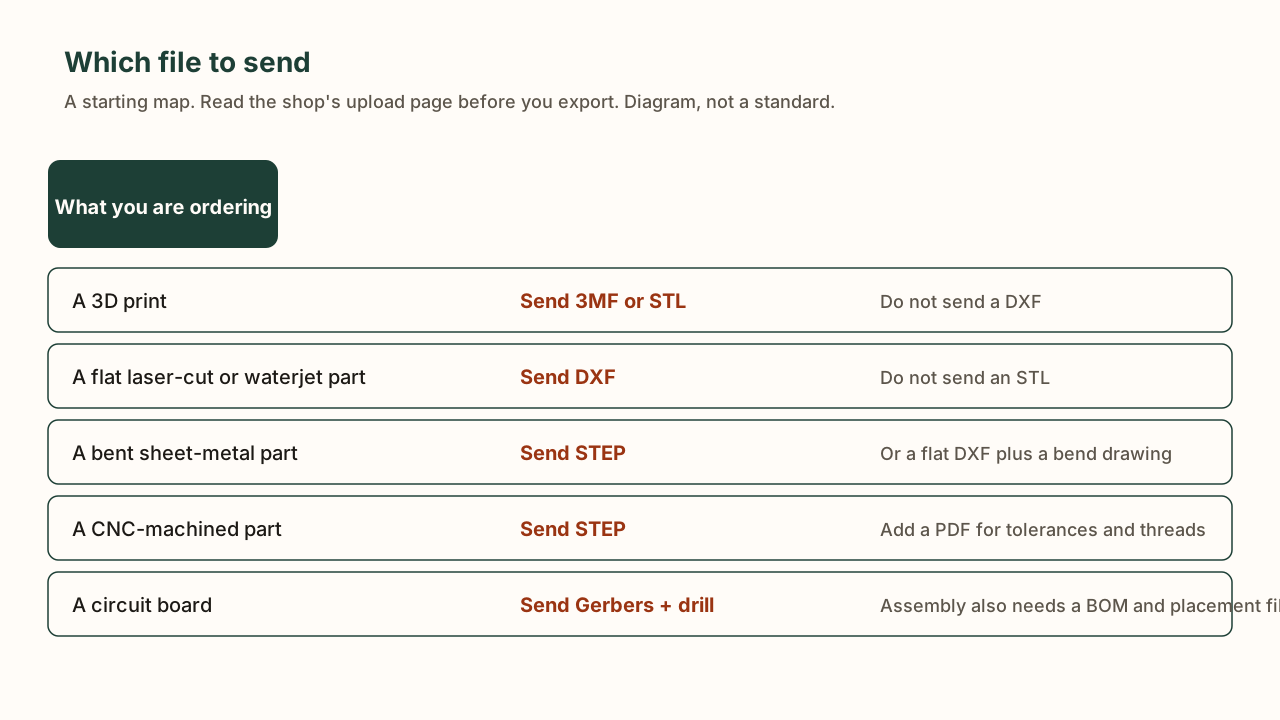
| You are ordering | Send | Also accepted | Do not send |
|---|---|---|---|
| A 3D print | 3MF or STL | STEP, at most services | A DXF |
| A flat laser-cut or waterjet part | DXF | SVG at hobby shops, STEP at some services | An STL |
| A bent sheet-metal part | STEP | A flat DXF plus a bend drawing | An STL |
| A CNC-machined part | STEP | A PDF drawing for tolerances and threads | An STL |
| A bare circuit board | Gerber files plus a drill file | A KiCad project, at some fabs | A picture of the board |
| An assembled circuit board | Gerbers, drill file, BOM and placement file | — | Gerbers alone |
Ask the AI for the editable source and the exact format, then make the shop’s file from that. A chatbot writing OpenSCAD usually gives you code that you export as STL or 3MF. A chatbot writing CadQuery or a text-to-CAD app that offers solids can often export STEP. Image-to-3D tools give you a mesh, which is fine for figurines and a poor fit for parts that must mate.
Converting between formats
- STEP to STL or 3MF is easy. Any CAD program or slicer can do it.
- STEP to DXF is easy for flat parts: export the top face as a 2D drawing.
- STL to STEP is hard. Converters wrap the triangles in a solid, which shops can open but not measure well. Rebuild the part instead.
- A picture to anything is not a conversion. It is a redraw.
Before you upload
- The format matches the process in the table
- Units are stated in the order notes
- You measured one known dimension in a viewer after export
- One part per file, unless the shop asks otherwise
- The file name carries a version, such as
bracket-v3.step
Prompting AI with numbers
AI tools draw what you specify, so specify everything. A reusable template:
Part: wall bracket for a 32 mm diameter tube.
Process and material: FDM, PETG, 0.4 mm nozzle.
Units: millimeters. Put every dimension in a named variable.
Critical dimensions: tube bore 32.4 mm (0.4 mm clearance), two 4.5 mm clearance holes for M4 countersunk screws, 50 mm apart.
Design rules: walls at least 2.4 mm (six 0.4 mm lines), no overhangs beyond 45°, 0.5 mm fillet on inside corners, 0.6 mm chamfer on the bed-side edges.
Orientation: printed on its back so the tube load runs along the layers.
Output: OpenSCAD code, then tell me the overall bounding box so I can check it in the slicer.
Limits: light-duty storage only. Nothing heavy, and nothing hung above people.
Adapt it per process:
- Laser or sheet metal: material and thickness, “DXF at 1:1 in mm, closed contours, one layer”, minimum hole of 50% of thickness for metal, and tabs and slots sized to the measured sheet, not the nominal one.
- CNC: material grade, tolerance per feature, “inside corner radius at least X mm”, standard thread callouts instead of modeled threads, STEP output.
- PCB: supply voltage (USB 5 V or a named battery), the exact module or chip, “use the fab’s DRC limits: 0.10 mm track and space minimum, via holes no smaller than 0.2 mm”, and “check every footprint against the datasheet”.
Then verify: measure the bounding box in the slicer or viewer, print a coupon, and send corrections back as numbers. The first-print fit checklist and why AI prints fail cover that loop.
Quick reference checklists
Before printing: units checked · walls ≥ 0.8 mm · overhangs ≤ 45° or supported · load along the layers · clearance coupon printed · filament dry · ventilation on.
Before lasering: material identified and on the approved list (no PVC or vinyl) · enclosure closed and interlocks working, or wavelength-matched eyewear for open machines · extraction on · someone with the machine for the whole job.
Before ordering: STEP or DXF at 1:1 · the shop’s own minimums applied · quote checked for material, quantity and shipping · import costs counted (ordering guide).
Before powering a board: DRC passed with fab limits · footprints checked against datasheets · low voltage only · first power-up current-limited.
FAQ
Which 3D printing process is the most accurate?
Of the common processes, resin (SLA) has the tightest tolerances and FDM is the least accurate, according to Protolabs Network. Powder processes such as SLS and MJF sit around ±0.3 mm in its table.
Do I need a hardened nozzle?
For carbon-fiber, glass-fiber and other particle-filled filaments, yes. Bambu Lab's filament guide says brass and stainless nozzles wear out quickly with these materials and recommends hardened steel.
What is the difference between a diode, CO2 and fiber laser?
Wavelength. Blue diodes (about 450 nm) suit wood, leather and dark opaque materials. CO2 lasers (10.6 µm) cut wood and clear acrylic well. Fiber lasers (1064 nm) mark and cut metals. UV lasers (355 nm) do fine marking on glass and plastics.
What laser class is safe at home?
A Class 1 product is safe in normal use. Many enclosed engravers are Class 1 only while the enclosure is closed and its interlocks work. Open-frame machines are often Class 4, which can injure eyes and skin even from scattered light and can start fires.
Which materials should never be laser cut?
PVC and vinyl, which release chlorine compounds, plus other halogenated plastics. University safety offices also list ABS, polycarbonate, HDPE, foams, coated carbon fiber and fiberglass as unsuitable. Check the safety data sheet and your machine's approved list.
Which file should I send to a print farm, laser shop or PCB fab?
Send 3MF or STL for a 3D print, a 1:1 DXF for a flat laser-cut or waterjet part, STEP for CNC or bent sheet metal, and Gerber files plus a drill file for a board. For assembly, add a bill of materials and a placement file. Confirm on the shop's upload page.
Can I send an STL to a laser cutter?
No. A laser needs a flat outline. Export a 1:1 DXF of the part's face from the original design, with closed contours and stated units.
Is 3MF better than STL?
For printing, yes: 3MF keeps units and colors. STL is still the format every tool accepts, but it has no units and a hole is only a ring of facets.
Why does a CNC or sheet-metal shop want STEP when my STL looks fine?
Quoting software reads exact faces, holes and bends. A triangle mesh has none of those. Keep STEP as the master file and make an STL from it when you need to print.
Is this guide sponsored?
No. Manufacturers and services are cited because they publish primary data. None reviewed or endorsed this guide, and links are plain links.