Electronics
Electronics and hardware for 3D-printed and laser-cut parts
A practical parts bin for cases and gadgets: microcontrollers, lighting, motion, power, fasteners, and the clearances to measure first.
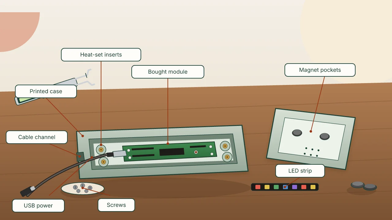
Sources: the official pages linked inline, including the Raspberry Pi Pico 2 W datasheet, Seeed Studio’s XIAO documentation, Adafruit’s NeoPixel Überguide and Li-ion and LiPoly guide, and CNC Kitchen’s heat-set insert guidelines. Project examples are from this site and are credited there. This is not a hands-on test of every part named. Nobody mentioned has reviewed or endorsed this article, and the links are plain links.
Not every vibe-manufactured object needs electronics. A kibble scoop or a tablet spoon is just a carefully measured piece of plastic. Many of the more interesting builds on this site are the other kind: a printed or laser-cut part that holds, hides or adapts something you bought.
The custom part is usually the case, the bracket or the adapter. The radio, the lock, the motor and the battery chemistry are not. Buy those, measure them, and let the AI draw the plastic around the real object.
The rule that saves a reprint
Buy the hardware first. Then measure it. Then ask for the case.
That is the same habit as the desk mute-button guide, which starts with a purchased USB module and a real button, and as a custom dog-door panel, which adapts a commercial lock rather than inventing one. Listing photos lie about hole spacing. Calipers and the datasheet don’t.
Dan Peguine’s method of printing small test coupons is the right way to check those fits. He tests screw posts, a PCB holder, an NFC-reader clip and grille patterns as little pieces, instead of reprinting the whole Button Box each time. Copy that for bosses, magnet pockets and connector cutouts.
If you’re unsure whether the object should even be a print, a laser-cut plate or a board, start with print, laser-cut or PCB?.
Gadgets with a microcontroller
A first electronics project can stay boring, and that is a virtue: a known board, USB power, one button or sensor, and a case that clears the plug.
Common boards, from their makers’ own docs:
| Board family | Why people pick it | What to measure before you model the case |
|---|---|---|
| Raspberry Pi Pico / Pico 2 W | Cheap, well documented, and already used in a real build on this site | The Pico 2 W datasheet gives a 51 mm × 21 mm × 1 mm PCB, 40 pins on a 2.54 mm pitch, four 2.1 mm mounting holes, and a micro-USB plug that overhangs the top edge. GPIO is 3.3 V. The wireless model has an antenna on the bottom edge: Raspberry Pi says no material should intrude into that space. |
| Seeed Studio XIAO | Very small (Seeed publishes a 21 × 17.8 mm form factor across the series) | The exact variant you bought, including the USB-C plug, any external antenna, and the battery pads if that model has them. One AI-designed board on this site was a tiny carrier between a lithium cell and a XIAO; treat that write-up as a case study, not a first project. |
| A named ESP32 development board | Built-in Wi-Fi and Bluetooth on many modules | Board outline, USB connector, button positions and antenna keep-out for that module. ESP32 boards are not one size. Federico Maggi’s DEF CON badge used an ESP32-S3, and a misunderstood switch stopped it booting until he removed it. |
| Arduino-compatible boards | Familiar software, huge examples | Logic voltage (some are 5 V, many newer boards are 3.3 V), the USB connector, and the mounting holes. Don’t mix 5 V signals into a 3.3 V pin. |
James Dean Garage’s lathe tap-box board is the grown-up version of the same idea. He started from a hand-wired Raspberry Pi Pico 2 W, a bought RS485 module and connectors, then had Claude Code drive KiCad to replace the bundle with a carrier. The board is a 5 V logic board. The servo drive and the machine power stayed off it.
You don’t need that custom PCB on day one. A module on headers, or even a module dropped into a printed tray, is enough to prove the case. The mute-button article says the same thing. If you later want an open-source editor that an AI agent can drive, rather than KiCad, see PCBCraft. It explains which repository documents Gerber export, and why the files still need a review before you order.
Displays, buttons and sound. Buy the part, then model the hole. A 0.96-inch I2C OLED, a 12 mm tactile switch, a speaker or a MEMS microphone all have datasheet outlines, and the plug or the wires need a path out. Anthropic and Diode’s speakerphone, voice hub and handheld pet show how far that can go — microphones, a speaker, an LED ring, USB-C, even a battery and a charger on the handheld — but those devices were built by engineers at a board house. At home, start with one button and USB, and add a display only after the board already runs.
NFC and wireless charging. Dan Peguine’s Button Box includes an NFC reader and a speaker, which is why he coupon-tests the reader clip. A magnetic charging pad is the other common pattern: Charlie Chapman designed a printed pad around a MagSafe or third-party puck, with a cable channel and versions sized for different puck diameters. He tested a 56 mm third-party puck and also offered fits for Apple’s published MagSafe charger diameter. Measure your own puck. Don’t copy a number from a photo.
Lighting
Addressable LED strips (often sold as NeoPixels, and typically based on chips such as the WS2812) are the usual way to add color to a printed diffuser or a ring around a gadget.
Adafruit’s NeoPixel Überguide is the source to read before you size a supply. It says each pixel draws up to 60 mA at maximum brightness white, and that a rough rule of thumb of about 20 mA per pixel is often enough when colors are mixed — but if you need every pixel full white, use the 60 mA figure. The same guide treats most strips as 5 V devices, and warns that a 3.3 V microcontroller may need a logic-level shifter when the strip is powered at 5 V.
Practical consequences for a printed part:
- A short accent (a few pixels) can often share USB power with the board. A long strip needs its own 5 V supply, sized from the figures above. Adafruit also notes that a typical Arduino board can supply only about 500 mA continuously from its 5 V pin, which is not enough for a busy strip.
- Design a cable path and a strain relief, and leave a way to get the strip out if a pixel dies.
- A printed diffuser works better with a small air gap than with LEDs jammed against the wall. Print a coupon of the gap and the wall thickness before the full lamp.
- This is low-voltage lighting only. Mains lamps, wall dimmers and mains LED drivers are not a prompt, and they are not covered here.
Motion
Bought motion plus a printed adapter is almost always better than a printed mechanism that tries to replace the motor.
- Hobby servos and small stepper motors. Measure the mounting-hole pattern, the shaft diameter and any flat on the shaft, and the body length. Give those numbers to the AI. Don’t ask it to invent a gearbox for a load you haven’t weighed.
- Rotary encoders. Matt Green’s classic Mini speedo-cable adapter is the pattern: three photos, caliper measurements, and a printed housing that lets a bought encoder (£16, his figure) read a mechanical cable. He thinned the flange to 4 mm because his M3 screws were only 6 mm long. “You still have to measure, and you still have to understand what you’re making,” he says.
- Bought actuators. A greenhouse vent-opener bracket adapts a commercial opener to a frame the included feet don’t fit. The cylinder stays a purchased product. The custom part is only the plate.
Keep motor current off a logic board you don’t understand. The lathe article is explicit: the Pico carrier is not a guide to wiring servo drives or machine power.
Power
Start on USB. A computer port, a USB wall wart or a USB power bank is the right first supply. Pick a board that already has the connector. Designing USB-C from scratch, including the configuration resistors, is a different project; the mute-button guide warns against inventing a USB stack when a module would do.
Lithium cells are not a first project. Two of the five AI-designed boards involve a lithium cell or a charger. Their writers are useful to read; their circuits are not a template. One builder first powered a XIAO battery adapter from a current-limited bench supply, which is the right instinct.
Adafruit’s Li-ion and LiPoly guide is clear that these cells “are not ‘safe’ batteries and require extra care,” and that charging or using them incorrectly can cause fire or explosion. From that guide and Adafruit’s product notes, the points that matter for a printed case are:
- Use a charger made for that chemistry. A protection circuit on the cell is not a substitute for a proper charger.
- Don’t puncture, crush, bend or short the pack, and don’t solder directly to the cell.
- Don’t leave charging unattended, and stop if the cell swells, heats, leaks or looks wrong.
- Don’t trap a pack in a sealed box with no room to swell and no way to remove it. Leave ventilation around regulators and cells, and keep packs out of hot cars. PLA already softens at modest temperatures; the getting-started guide cites Bambu Lab’s note that PLA is not recommended at about 50 °C or higher.
If you later need a portable gadget, a USB power bank with its own certified enclosure is a simpler first step than a loose pouch cell in a printed shell. This page will not walk through charger schematics, and it will not help with mains supplies.
Fastening: screws, inserts, magnets and bearings
Small printed threads are weak. The advanced guide already lists the usual alternatives: a heat-set brass insert, a captive hex nut in a pocket, or a self-tapping screw into a plain hole.
Heat-set inserts. Use the hole size and the minimum wall thickness from the maker’s datasheet, not a guess. Make the blind hole about 1 mm deeper than the insert, as CNC Kitchen’s design guidelines recommend, and add a fillet or a short rib at the base of the boss so it doesn’t snap off. Stefan of CNC Kitchen has also shown, in a later test, that printed holes often come out undersized; he suggests adding about 0.2 to 0.3 mm in CAD for smaller inserts after you test your own printer and filament. He sells the inserts, so treat those figures as tests by an interested party, and still print a coupon.
A soldering iron used for inserts is hot enough to burn you and to scorch plastic. Work on a protected surface, in a ventilated space, and put the iron back in its stand.
Screws you already own. Matt Green’s 6 mm M3 screws are a reminder to measure fastener length, not just diameter. Countersinks need a matching screw head. Through-holes need clearance on one side and a nut or an insert on the other. M2, M2.5 and M3 cover most small boards; Raspberry Pi’s own Pico 2 W drawing uses 2.1 mm mounting holes, which suit an M2 screw with a little clearance.
Magnets. Design a pocket around a magnet you have measured, with a tested gap, and either a printed cap or a drop of adhesive so it can’t fall out. Charlie Chapman’s pad is a charging puck in a cutout, not a loose magnet, but the measurement habit is the same. Strong neodymium magnets can pinch skin, damage some credit cards and watches, and interfere with implanted medical devices; keep them away from people who have those devices, and don’t leave loose magnets near children.
Bearings and metal pins. Buy the bearing or the pin, then model the seat to the maker’s dimensions plus a clearance you have tested. Don’t ask the AI for a “standard bearing” without a part number.
Adhesives. Cyanoacrylate and two-part epoxy will join printed parts and will retain a magnet. Hot glue is handy for a temporary wire strain relief and can soften if the board or the room gets warm. None of these is a substitute for a screw in a part you may need to open.
Design tips for the case itself
These sit beside the first-print fit checklist and the design rules in the advanced guide.
- Clearances. This site uses 0.2–0.4 mm as a starting estimate for a slip fit on many FDM printers. It is an estimate. Print a coupon on your machine.
- Screw bosses. Give the boss a wall at least as thick as the insert maker’s minimum, a fillet at the root, and enough height for the insert plus that extra millimeter. Dan Peguine prints several boss variants as coupons and keeps the one that works.
- Cable routing. Leave a channel, a slot or a gland for every cable, including the USB plug’s over-mold, which is larger than the metal shell. Charlie Chapman’s pad has an explicit cable channel. Add a simple strain relief so a tug hits the case, not a solder joint.
- Ventilation. Even a USB gadget can warm a regulator. Charlie Chapman put holes in the bottom of his pad “just to take less material / ventilation.” Leave a path for air, and a way to get the board out.
- Antenna keep-out. For a Pico 2 W or any board with an onboard antenna, copy the keep-out from the datasheet. A tight plastic wall over the antenna is a common way to make a wireless project disappointing.
- Lids. A printed lid with inserts is one option. A laser-cut acrylic or plywood lid, sized to a measured recess, is another, and is often flatter. That’s a good use of a DXF.
- Don’t scale the whole model to correct one tight hole. Change that one dimension. The fit tips and Confetti’s card-shuffler build plan both say this.
A starter kit
No prices, because they change, and no affiliate links. This is a shopping list of kinds of part, not a cart.
- Digital calipers, and a notebook for millimeters.
- A multimeter.
- One microcontroller board you can program, plus a USB cable that actually carries data.
- A breadboard and jumper wires, so the first circuit exists before the case does.
- A small assortment of M2, M2.5 and M3 screws and nuts, in a few lengths.
- Heat-set inserts in those sizes, and a soldering iron with a stand.
- A few momentary buttons, and optional: a small I2C display you will measure.
- A short run of 5 V addressable LED strip, only if you want lights.
- A handful of disc magnets in one size, measured with the calipers.
- Heat-shrink tubing, and a little cyanoacrylate or epoxy.
- Optional, later: a small hobby servo or a rotary encoder, bought as a named part, and a USB power bank rather than a loose lithium cell.
You can start for less than this. The getting-started guide’s first projects — a clip, a knob, a hook — need only calipers and filament.
Common mistakes
| Mistake | What happens | Fix |
|---|---|---|
| Designing the case before the module arrives | The USB plug hits the wall, or the holes miss | Buy and measure first |
| Trusting a product photo for hole spacing | Screws don’t line up | Datasheet, then calipers on the part in your hand |
| Printed threads on an M2 or M3 screw | Threads strip after a few openings | Insert, captive nut, or a tested self-tapping hole |
| Powering a long LED strip from the board’s 5 V pin | The board browns out or resets | Size the supply from Adafruit’s figures; separate the strip’s power when it is more than a few pixels |
| No antenna keep-out | Wireless range collapses | Copy the keep-out from the board’s datasheet |
| A loose LiPo in a sealed shell | Heat, swelling, and no way to inspect the pack | USB first; if you later use a cell, use a proper charger and leave access and ventilation |
| Mixing 5 V and 3.3 V | A damaged pin or a silent logic error | Check the board’s logic level; shift levels if needed |
| Inventing USB-C, a lock, or a mains supply | A case around a dangerous or unfinished circuit | Buy the certified module; keep this work on low voltage |
| Scaling the whole STL to fix one hole | Every other fit goes wrong | Change one dimension, or print a coupon |
Safety, in one place
- Low voltage only. USB or a small, bought battery system. No mains in a printed or laser-cut box, and no advice on wiring the wall.
- Lithium cells. Follow the maker and a guide such as Adafruit’s, as summarized above. This is not a charger-design article.
- Heat. Soldering irons, heated beds and insert tools burn. Work with a stand, and don’t leave a hot iron down on the bench.
- Lasers and fumes. If the lid is laser-cut, follow the laser safety notes in the advanced guide: enclosure and interlocks, rated eyewear when the machine isn’t fully enclosed, never leave a job unattended, and never cut PVC or vinyl.
- Magnets. Pinch, data-card and medical-device hazards, as above.
- Children. Buttons, magnets, coin cells and small screws are swallowable. A printed gadget is not a toy unless you have designed it as one, with those risks in mind.
- Don’t print safety parts. If the part holds a person, a heavy load overhead, or fuel, buy rated hardware, the same rule as the rest of this site.
If you’re new, start with the getting-started guide, make one USB-powered box that fits a board you measured, and come back to this list when you add a fastener, a light or a bought motor.
FAQ
Do I need a custom PCB before I print a case?
No. A first gadget can be a bought microcontroller module, a button and a case that fits those parts. A custom board is a later pass, once the module and the case already work, as the desk mute-button guide describes.
Which microcontroller should I start with?
Pick one board you can already program, or are willing to learn from its official docs: a Raspberry Pi Pico or Pico 2 W, a Seeed Studio XIAO, or a named ESP32 development board. Buy that exact board first, then measure it. Don't prompt a case for a board you haven't got.
Is it safe to put a LiPo battery in a printed case?
Not as a first project. Start on USB power or a USB power bank. Lithium cells need a proper charger, a protection circuit, and careful handling; a printed box does not add those. This article is not a how-to for charging circuits. See the safety section and Adafruit's Li-ion and LiPoly guide.
What hole size should I use for heat-set inserts?
Use the hole diameter and minimum wall from the insert maker's datasheet, then print a small test coupon. Printed holes often come out smaller than in the file. CNC Kitchen, which also sells inserts, suggests adding about 0.2 to 0.3 mm in CAD for smaller inserts after you test your own printer.
Does this page recommend specific shops or include affiliate links?
No. Tools, boards and makers are named as public examples. Nobody named here has reviewed or endorsed this article, and the links are plain links with no tracking or affiliate codes.
Can I put mains electricity in a 3D-printed enclosure?
No. Stay on USB or other low-voltage supplies. Mains wiring, lamp dimmers and wall-plug supplies are out of scope here, and a generated case file does not make them safe.